
Synchronous servo channel for tape drive systems

a technology of synchronous servo and drive system, which is applied in the direction of data recording, magnetic recording, instruments, etc., can solve the problems of no reliable lpos detection, no monitoring of time evolution, and no reliable reliability measurement, so as to avoid coupling

Inactive Publication Date: 2008-04-29
INT BUSINESS MASCH CORP
View PDF28 Cites 33 Cited by
  • Summary
  • Abstract
  • Description
  • Claims
  • Application Information

AI Technical Summary

Benefits of technology

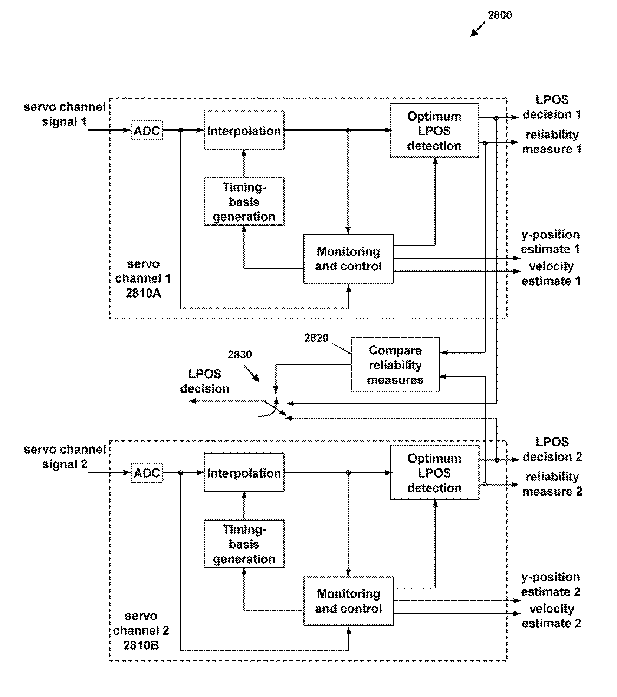
The present invention provides a fully synchronous servo channel that can automatically acquire synchronous servo channel parameters, generate a timing basis for signal interpolation, and estimate the tape velocity and y-position. This is done without relying on any previously known measure of tape velocity or drive motor current. The invention also optimizes the detection of longitudinal position (LPOS) symbols by assigning a reliability measure or value to the detection output. This allows for the selection of the symbol with the most reliable detection based on the results of two parallel servo channels.

Problems solved by technology

This approach has the following severe limitations:a) The A / D converter sampling frequency has to change with the tape velocity if a constant rate expressed in number of samples per micrometer that is independent of tape velocity is desired.
If a fixed sampling frequency is adopted, the rate depends on the tape velocity.b) A consequence of the choice of a fixed sampling rate is that the number of samples per dibit response at the LPOS detector (peak detector) is variable depending on the velocity.c) No reliable LPOS detection is possible during acceleration and deceleration, i.e., during the phase at which the velocity is changing towards the target velocity.d) Peak detection is not the optimum detection scheme for the LPOS pattern, which is generated using pulse position modulation (PPM) techniques.e) There is no possibility to monitor the time evolution of the signal at the output of the servo channel since there is no time reference.f) There is no possibility to have a measure of reliability of the LPOS detection process.
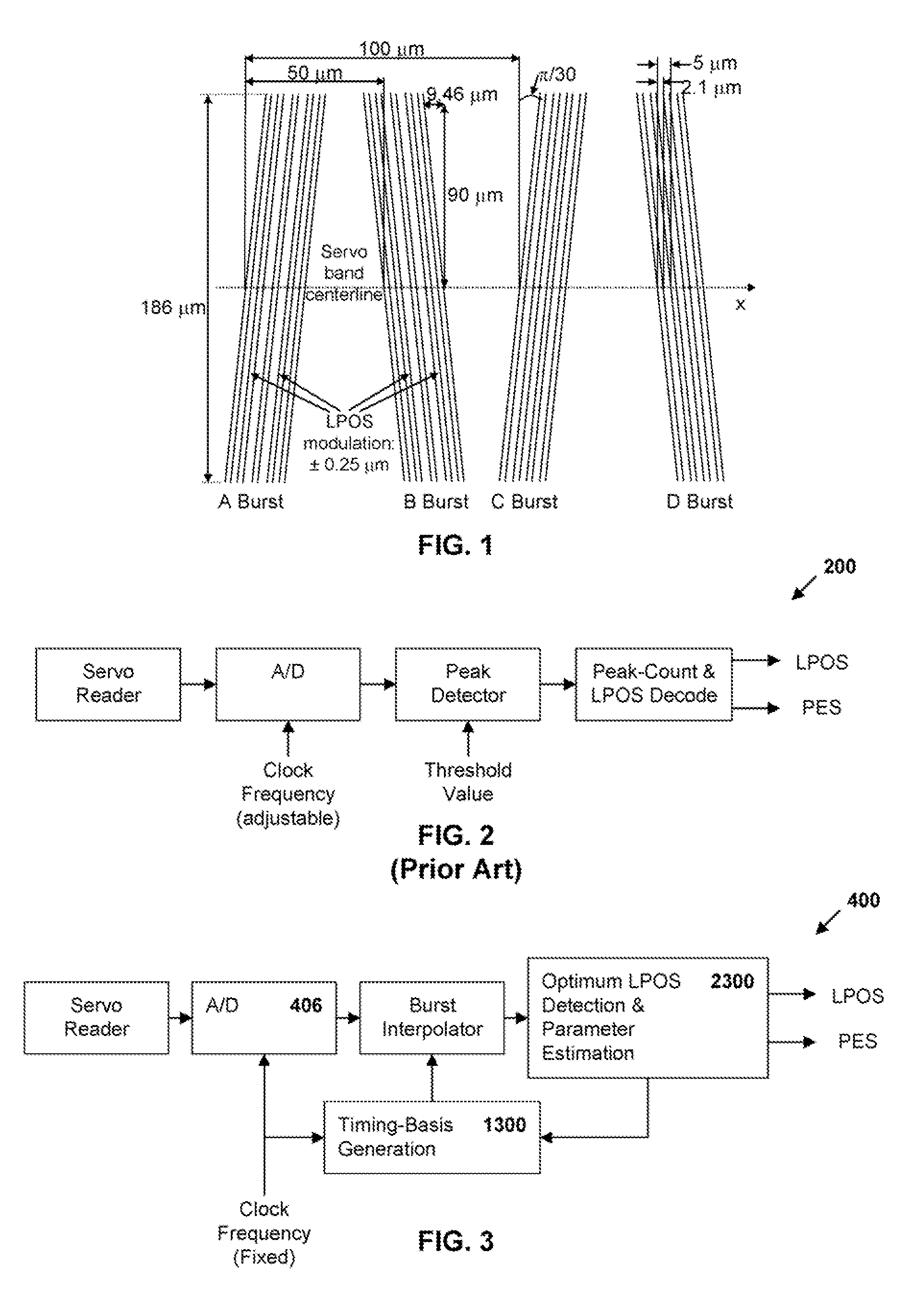
Clearly, such a resolution is not adequate when one wants to resolve LPOS pulse position modulation of + / −0.25 μm.

Method used


Image

  • Synchronous servo channel for tape drive systems
  • Synchronous servo channel for tape drive systems
  • Synchronous servo channel for tape drive systems

Examples


Embodiment Construction

Synchronous Servo Channel Architecture

[0046]With the architecture of the present invention, the dynamic interpolator allows any sampling rate at the detector input, with the only limitation arising because of potential aliasing effects. For example, in the case of a distance between magnetic transitions given by Lp=2.1 μm, the maximum velocity achievable without aliasing effects with a 15 MHz fixed ADC clock is νmax=2.1×(15 / 2)=15.75 m / s. In this case the equivalent sampling frequency after the burst interpolator for achieving a resolution of 0.05 μm is equal to 315 MHz. Note that this would be the required fixed sampling frequency in an asynchronous architecture.

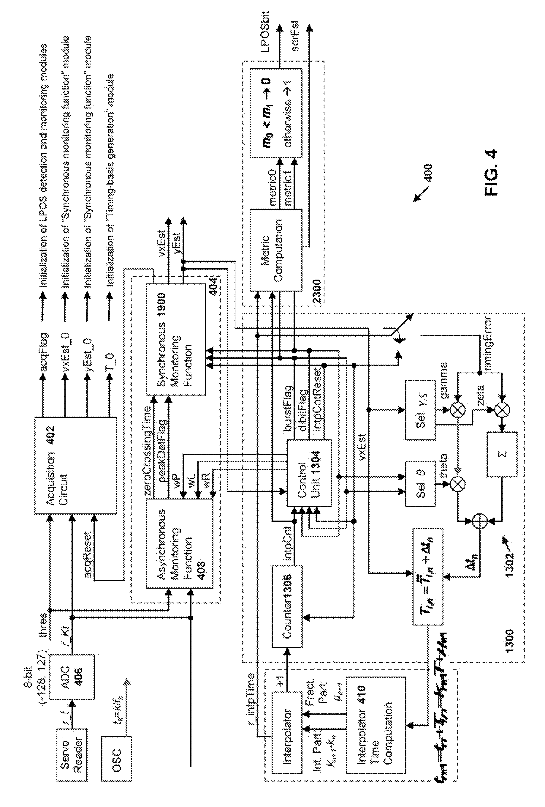
[0047]FIG. 3 illustrates the basic building blocks of the synchronous LPOS detection architecture 400 of the present invention. Because the number of samples per unit of length is fixed and independent of velocity after the burst interpolator, a matched filter approach can be employed for optimum detection of PPM in the pres...


PUM

PropertyMeasurementUnit
equivalent sampling frequencyaaaaaaaaaa
velocitiesaaaaaaaaaa
velocityaaaaaaaaaa

Abstract

A fully synchronous servo channel for a data type drive is provided which includes the initial acquisition of synchronous servo channel parameters, generation of a timing basis for signal interpolation, generation of a tape velocity estimate and a y-position estimate and an optimum detection of longitudinal position (LPOS) symbols embedded in servo bursts.

Description

RELATED APPLICATION DATA[0001]The present application is related to commonly-assigned and co-pending U.S. application Ser. No. 11 / 340,030, entitled SYNCHRONOUS SERVO CHANNEL FOR LONGITUDINAL POSITION DETECTION AND POSITION ERROR SIGNAL GENERATION IN TAPE DRIVE SYSTEMS, filed on Jan. 26, 2006, which application is incorporated herein by reference in its entirety.TECHNICAL FIELD[0002]The present invention relates generally to servo channel architecture in a magnetic tape storage system and, in particular, to a synchronous servo channel architecture.BACKGROUND ART[0003]Timing-based servo (TBS) is a technology developed specifically for linear tape drives in the late '90s. In TBS systems, recorded servo patterns consist of transitions with two different azimuthal slopes, and head position is derived from the relative timing of pulses generated by a narrow head reading the pattern. TBS patterns also allow the encoding of additional longitudinal position (LPOS) information without affecti...

Claims


Application Information

Patent Timeline
Patent Type & Authority Patents(United States)
IPC IPC(8): G11B15/52
CPCG11B5/59688
Inventor CHERUBINI, GIOVANNIELEFTHERIOU, EVANGELOSHUTCHINS, ROBERT ALLANJELITTO, JENS
Owner INT BUSINESS MASCH CORP
Learn More