Synchronization detecting apparatus

a detection apparatus and synchronization technology, applied in the direction of synchronization arrangement, multiplex communication, baseband system details, etc., can solve the problems of poor reception quality, inability to obtain the trigger for releasing the channel, and poor reception quality

Inactive Publication Date: 2008-04-29
FUJITSU LTD
View PDF29 Cites 6 Cited by
  • Summary
  • Abstract
  • Description
  • Claims
  • Application Information

AI Technical Summary

Problems solved by technology

Accordingly, a trigger for releasing the channel cannot be obtained despite a long wait, although the portable terminal must terminate the communication and the channel must be released.
It is proved from this figure that if reception quality is deteriorated, an error rate and a non-error rate become equal, and the error rate results in 0.5.

Method used


Image

  • Synchronization detecting apparatus
  • Synchronization detecting apparatus
  • Synchronization detecting apparatus

Examples


Embodiment Construction

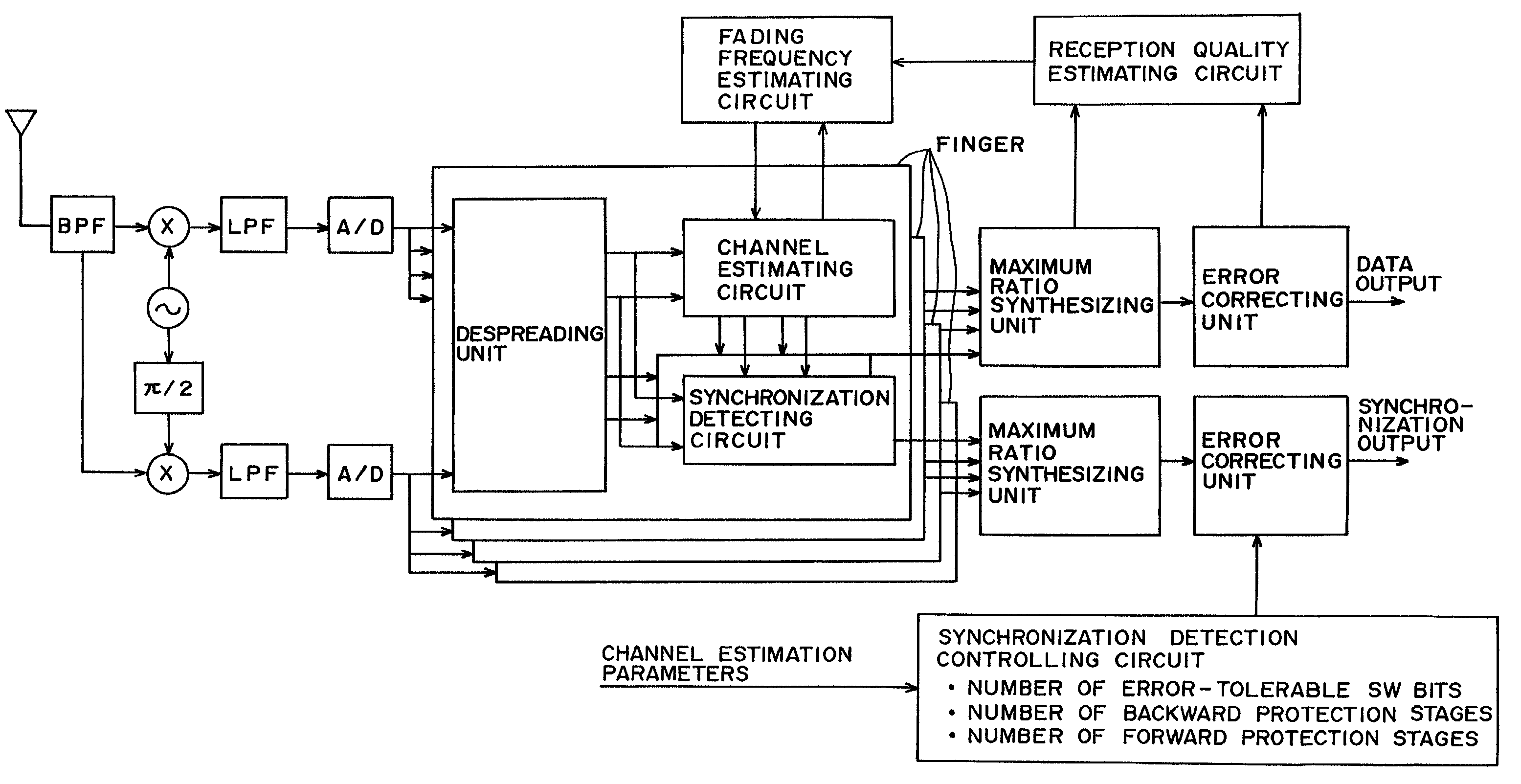
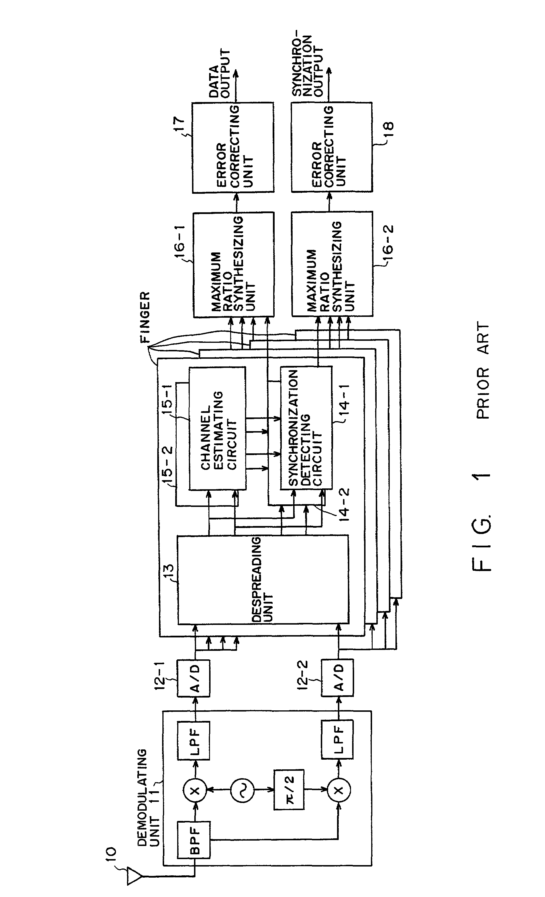
[0039]The following description omits the explanations of the same constituent elements as those of the receiver shown in FIG. 1.

[0040]In preferred embodiments according to the present invention, if the correlation between a channel estimation value and a SW bit is expected to be strong, the SW bit is removed from the channel estimation value to weaken the correlation with the SW bit to be demodulated. This is because an SW cannot be properly detected if the correlation between a channel estimation result and an SW bit to be demodulated is strong.

[0041]With the above described method, the correlation between a channel estimation value and an SW bit is removed, thereby properly detecting an SW.

[0042]FIG. 7 shows a first preferred embodiment according to the present invention.

[0043]This figure shows 1 slot of the channel estimating circuit exemplified in FIG. 3. If a symbol to be demodulated is a symbol P1 as shown in FIG. 7, this symbol is demodulated with a channel estimation value ...


PUM


Abstract

In a channel estimating circuit, a Sync Word is demodulated by using a channel estimation value not with a symbol or a slot including the Sync Word to be demodulated, but with its preceding and succeeding symbols or slots. Furthermore, in a channel estimation process, if a Synch Word to be demodulated is included in any of groups into which a plurality of symbols are divided, the Sync Word is demodulated by using a channel estimation value obtained with the channel estimation process using not this group but another group.

Description

BACKGROUND OF THE INVENTION[0001]1. Field of the Invention[0002]The present invention relates to a synchronization detecting apparatus for a wireless signal transmission line, which is comprised by a CDMA (Code Division Multiple Access) system receiver.[0003]2. Description of the Related Art[0004]A CDMA system attempts to improve its reception quality by using RAKE reception, which is pat diversity (plus space diversity reception (antenna diversity reception)). In a signal format of a W-CDMA (Wideband Code Division Multiple Access) system, a synchronization signal (Sync Word: hereinafter referred to simply as an SW) for detecting synchronization is multiplexed on a pilot signal, and the SW is demodulated by a receiver to detect synchronization. The RAKE receiver makes estimation (channel estimation) for the stare of a propagation path by using a pilot signal included in a reception signal containing a lot of noise, makes synchronization detection, and the synthesizes pats so as to d...

Claims


Application Information

Patent Timeline
IPC IPC(8): H04B1/00H04B1/707H04B1/7073H04B7/26H04L7/00H04L25/02H04W56/00
CPCH04B1/7075H04L25/0232H04B2201/70701
Inventor MINOWA, MORIHIKOKIMURA, DAIKAWAGUCHI, NORIYUKI
Owner FUJITSU LTD
Why Eureka
Try Eureka