Oscillation driver circuit, oscillation driver device, physical quantity measurement circuit, physical quantity measurement device, and electronic instrument

a driver circuit and oscillation technology, applied in the direction of turn-sensitive devices, instruments, pulse techniques, etc., can solve the problems of considerable difficulty in achieving a quick transition to normal operation, and the inability to form circuits using common circuits

Inactive Publication Date: 2009-04-02
SEIKO EPSON CORP
View PDF7 Cites 41 Cited by
  • Summary
  • Abstract
  • Description
  • Claims
  • Application Information

AI Technical Summary

Benefits of technology

[0016]Moreover, it is necessary to prevent a situation in which the vibrator breaks down due to an overcurrent in the low power consumption mode and the normal operation mode.

Problems solved by technology

However, since different characteristics are required for the gain control amplifier (GCA) that adjusts the voltage amplitude of a sine-wave signal and the circuit (e.g., comparator) that generates the rectangular-wave synchronous detection reference signal, these circuits cannot be formed using a common circuit.
In particular, when using a crystal vibrator, it is considerably difficult to achieve a quick transition to a normal operation due to an increase in startup time.

Method used


Image

  • Oscillation driver circuit, oscillation driver device, physical quantity measurement circuit, physical quantity measurement device, and electronic instrument
  • Oscillation driver circuit, oscillation driver device, physical quantity measurement circuit, physical quantity measurement device, and electronic instrument
  • Oscillation driver circuit, oscillation driver device, physical quantity measurement circuit, physical quantity measurement device, and electronic instrument

Examples


first embodiment

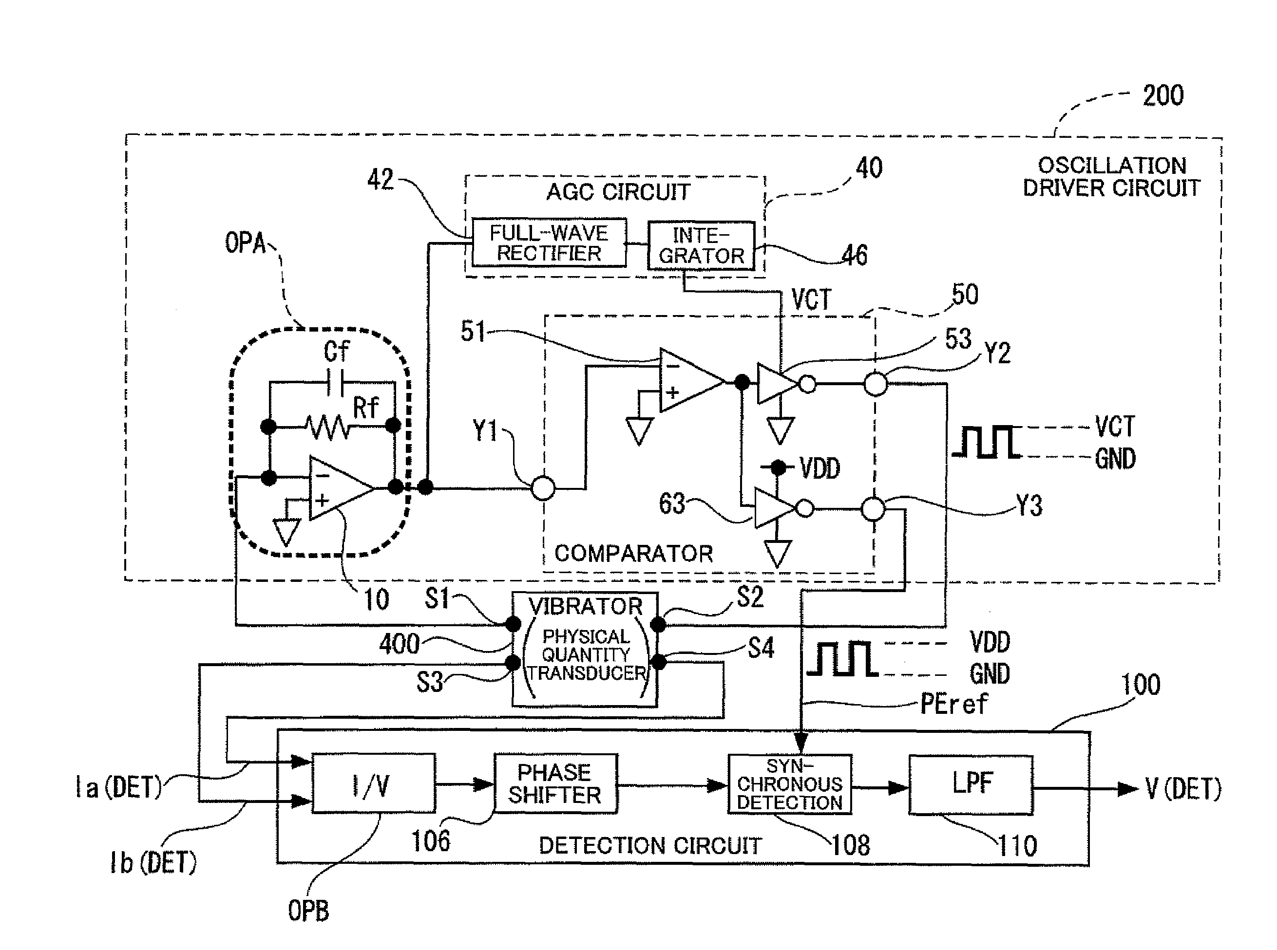
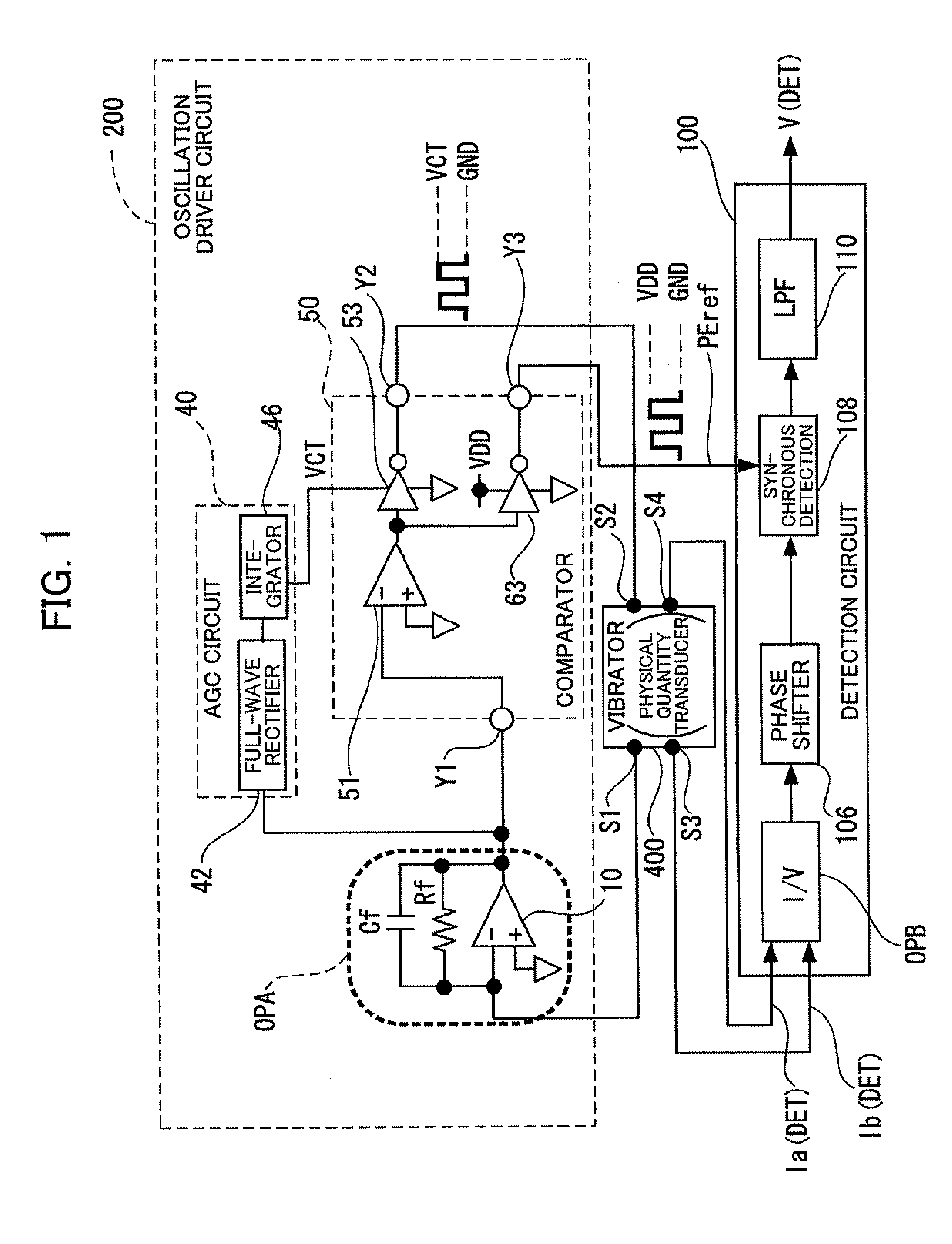
[0121]An outline of the main embodiment of the invention is given below. FIG. 1 is a circuit diagram showing the configuration of a physical quantity measurement device (including an oscillation driver circuit, a detection circuit, and a physical quantity transducer) according to the invention. The main configuration and the operation of the physical quantity measurement device according to this embodiment are described below.

[0122]Oscillation conditions during oscillation startup and stable oscillation state

[0123]An oscillation driver circuit 200 drives a physical quantity transducer 400 by means of an oscillation loop. The loop gain of the oscillation driver circuit 200 according to this embodiment is set to be larger than unity during oscillation startup in order to enable high-speed startup. Specifically, the oscillation conditions during oscillation startup are satisfied when the loop gain is larger than unity and the phase in the loop is 360°×n (n is an integer). The oscillati...

second embodiment

[0204]This embodiment illustrates a specific circuit configuration example of the composite comparator (two-stage-output comparator with shared differential section) 51.

[0205]Specific Circuit Configuration Example of Composite Comparator

[0206]FIG. 7 is a circuit diagram showing an example of a specific circuit configuration of the composite comparator. As shown in FIG. 7, the comparator 51 includes a constant current source IS, a differential section (differential circuit) QS (reference numeral 51 in FIGS. 1 to 6), and first and second output sections (Pout1 and Pout2: reference numerals 53 and 63 in FIGS. 1 to 6).

[0207]The constant current source IS includes a constant current circuit (QL) that generates a constant current I2, NMOS transistors (M1 and M2), and a PMOS transistor (M3). The NMOS transistors (M1 and M2) form a current mirror.

[0208]The differential section (QS) includes a PMOS transistor M4 that supplies an operating current, differential-pair transistors (M5 and M6), a...

third embodiment

[0216]This embodiment illustrates a specific configuration example of the AGC circuit 40. FIG. 9 is a circuit diagram showing a specific circuit configuration of an example of the AGC circuit.

[0217]As shown in FIG. 9, the AGC circuit 40 includes the full-wave rectifier 42, the oscillation detector 44, and the integrator 46.

[0218]The full-wave rectifier 42 subjects the alternating-current voltage signal from the current / voltage conversion amplifier circuit (OPA) to full-wave rectification to obtain a voltage having only a positive waveform, for example. The full-wave rectifier 42 includes an operational amplifier (OP2) that includes an input resistor R2 and a feedback resistor R3, switches (45 and 47) that are complementarily turned ON, and a comparator (OP3) that causes the switches (45 and 47) to be turned ON / OFF.

[0219]The integrator 46 generates the gain control signal (VCT) for controlling the gain in the oscillation loop based on an integration result for the voltage value conve...


PUM


Abstract

An oscillation driver circuit that drives a physical quantity transducer includes a one-input/two-output comparator. The one-input/two-output comparator includes a shared differential section that compares a voltage signal input from a drive current/voltage conversion amplifier circuit with a given voltage, a first output section that receives a signal output from the differential section, variably adjusts a voltage amplitude of the received signal, and outputs the resulting signal, and a second output section that receives the signal output from the differential section, and outputs a synchronous detection reference signal of which the voltage amplitude is fixed.

Description

[0001]Japanese Patent Application No. 2007-192400 filed on Jul. 24, 2007, is hereby incorporated by reference in its entirety.BACKGROUND OF THE INVENTION[0002]The present invention relates to an oscillation driver circuit, an oscillation driver device, a physical quantity measurement circuit, a physical quantity measurement device (e.g., vibrating gyrosensor), an electronic instrument, and the like.[0003]Gyrosensors are classified as a rotating gyrosensor, a vibrating gyrosensor, and the like depending on the method of detecting the force applied to an object. In particular, a vibrating gyrosensor is considered to be advantageous for reducing size and cost from the viewpoint of the constituent elements and the like.[0004]A vibrating gyrosensor that detects an angular velocity causes a physical quantity transducer (vibrator) to produce driving vibrations in a specific direction. When an angular velocity is applied to the vibrator, a Coriolis force occurs perpendicularly to the drivin...

Claims


Application Information

Patent Timeline
Patent Type & Authority Applications(United States)
IPC IPC(8): H03K3/00G01P15/14G01C19/56G01C19/5776
CPCG01F1/8431G01F1/8422
Inventor YOSHIDA, NAOKIKANAI, MASAHIROOTSUKA, EITARO
Owner SEIKO EPSON CORP
Why Eureka
Try Eureka