PLC for connecting optical fibers to optical or optoelectronic devices

a technology of optical fibers and optical or optoelectronic devices, applied in the field of planar lightwave circuits, can solve the problem that the method of connecting to submicron waveguides is not readily used

Active Publication Date: 2008-04-29
CISCO TECH INC
View PDF6 Cites 57 Cited by
  • Summary
  • Abstract
  • Description
  • Claims
  • Application Information

AI Technical Summary

Problems solved by technology

Fiber optic cables have typically been edge connected to the sides of optical and optoelectronic integrated circuits, but this method is not readily useable f

Method used


Image

  • PLC for connecting optical fibers to optical or optoelectronic devices
  • PLC for connecting optical fibers to optical or optoelectronic devices
  • PLC for connecting optical fibers to optical or optoelectronic devices

Examples


Embodiment Construction

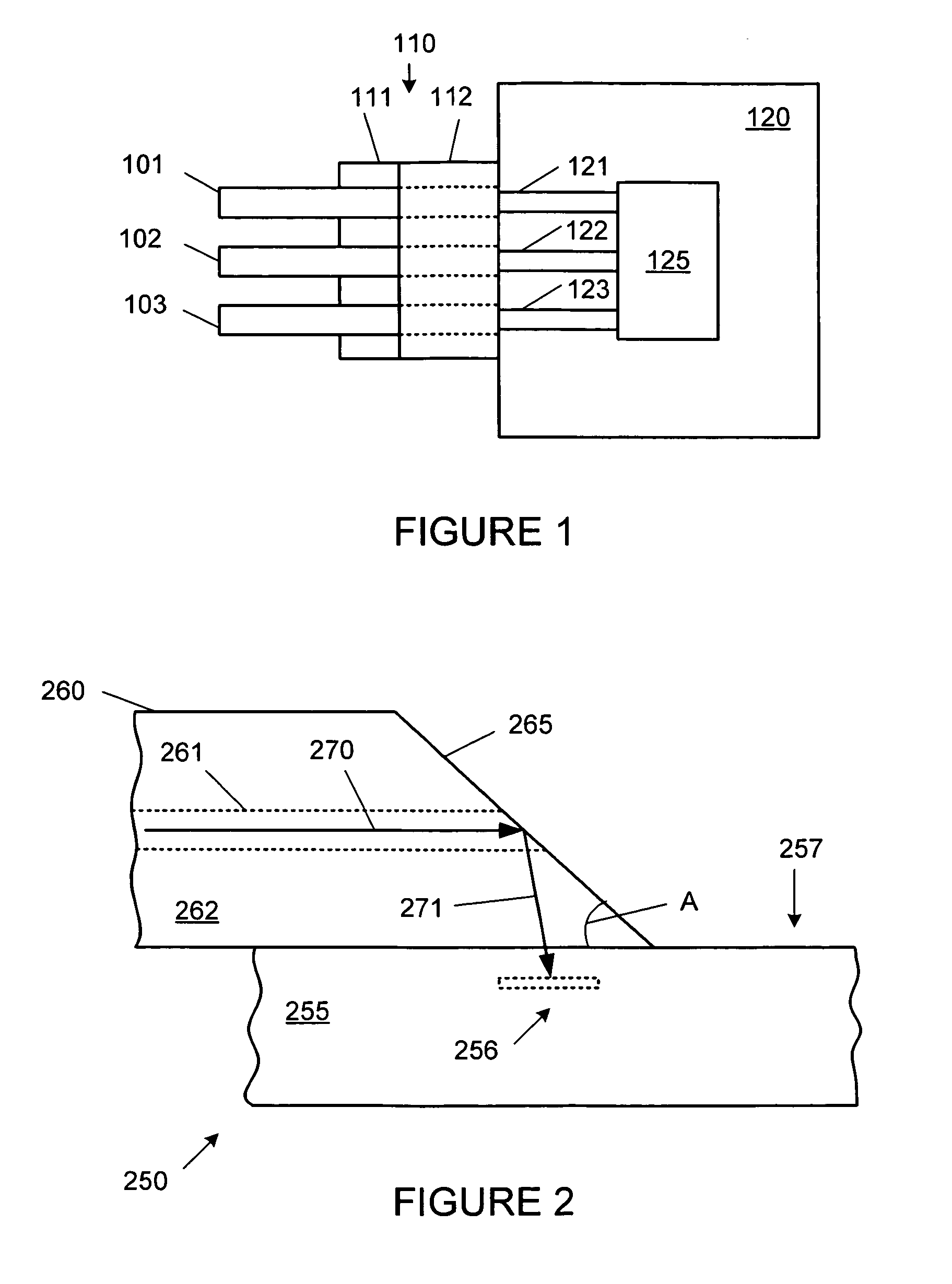
[0018]FIG. 1 is a top view, not to scale, of a prior art fiber array 110 used to connect a plurality of optical fibers 101, 102 and 103 to the side of an optical integrated circuit 120. Fiber array 110 connects fiber optic cables 101, 102 and 103 to the planar optical waveguides 121, 122 and 123 of optical integrated circuit 120. Waveguides 121, 122 and 123 of integrated circuit 120 are connected to optical device 125 on integrated circuit 120. Fiber array 110 includes pedestal 111 and cover 112. Pedestal 111 typically has a series of v-grooves, which hold optical fibers 101, 102 and 103 so that the fibers can be connected to the side of integrated circuit 120. The v-grooves on pedestal 111 are spaced apart from each other, typically in an equi-distant manner, to match the spacing between the waveguides on integrated circuit 120. Cover 112 holds the fibers in position and can be glued or mechanically attached to pedestal 111.

[0019]Connecting optical fibers 101, 102 and 103 directly ...


PUM


Abstract

Planar lightwave circuit (PLC) connects optical fibers to the top of an optical or optoelectronic device or optical or optoelectronic integrated circuit. Light propagating through optical fibers is directed to optical waveguides disposed on optical devices. The optical fibers can be in the form of individual fibers, a fiber ribbon or a fiber array. Fiber optic cables can be plugged into a ferrule attached to the PLC. The PLC can also include optical components integrated into the optical path between the optical fibers and the optical device.

Description

FIELD OF THE INVENTION[0001]The present invention relates to a planar lightwave circuit (PLC) for connecting optical fibers to the top of an optical or optoelectronic device or optical or optoelectronic integrated circuit and providing a low loss optical coupling between the fibers and the device or integrated circuit.BACKGROUND OF THE INVENTION[0002]Optical fibers have been widely used for the propagation of optical signals, especially to provide high speed communications links. Optical links using fiber optics have many advantages compared to electrical links: very large potential bandwidth, high noise immunity, reduced power dissipation and minimal crosstalk.[0003]Recent advances in the fabrication of silicon based optical and optoelectronic integrated circuits have resulted in the making of optical waveguides with submicron cross sectional dimensions. Fiber optic cables have typically been edge connected to the sides of optical and optoelectronic integrated circuits, but this me...

Claims


Application Information

Patent Timeline
IPC IPC(8): G02B6/26G02B6/42
CPCG02B6/4214G02B6/421G02B6/4249
Inventor PETERSON, MARKHARRISON, MARK
Owner CISCO TECH INC
Why Eureka
Try Eureka