Method and system for maneuvering movable object

a technology for moving objects and maneuvering methods, applied in the direction of steering initiations, navigation instruments, instruments, etc., can solve the problems of large amount of power, deviation from the desired ship course, and inability to cope with situations, so as to minimize power in compliance

Active Publication Date: 2008-04-29
KAWASAKI HEAVY IND LTD
View PDF17 Cites 35 Cited by
  • Summary
  • Abstract
  • Description
  • Claims
  • Application Information

AI Technical Summary

Benefits of technology

[0008]The present invention is directed to overcoming the foregoing drawbacks and a primary object of the invention is therefore to provide a movable object maneuver method and system capable of automatically track-keepig a movable object so as to track an optimum route which passes a desired destination point, while minimizing power in compliance with given constraints.
[0009]The object can be accomplished by a method and system for maneuvering a movable object according to the invention, wherein a destination point is set, wherein a thrust value is calculated in real time which minimizes or maximizes a performance index associated with one or more state variables and thrust required for a movable object to reach the destination point and which takes into account non-linear conditions inherent to the movable object, and wherein the movable object is moved based on the calculated thrust value. This obviates not to need for calculating a route beforehand like the prior art and controls the movable object through actual position control while calculating an optimum route directed to the destination point in real time, so that even if disturbances affect the movable object, it can automatically track the optimum route with the minimum power that meets given conditions.
[0010]According to the invention, there are provided a method and system for maneuvering a movable object wherein a destination point is set, a thrust value is calculated in real time which minimizes or maximizes a performance index associated with a thrust required for a movable object to reach the destination point, and the movable object is moved based on the calculated thrust value; and wherein one or more transit points arc set on a planned route for the movable object and on or more set transit points arc sequentially set as the destination point. This enables the optimum movement that is not bound by the route more than necessary so that power can be considerably reduced compared to the case of faithful tracking of the route.

Problems solved by technology

This consumes a great amount of power in some cases.
In addition, since a turn with a fixed turn rate (i.e., feed forward control) is made in the course change operation, there arises the possibility that the deviation from the desired ship course increases.
This technique is useful where the advent of obstacles is predictable, but cannot cope with situations where obstacles unexpectedly appear or move because the functions are time invariant.

Method used


Image

  • Method and system for maneuvering movable object
  • Method and system for maneuvering movable object
  • Method and system for maneuvering movable object

Examples


first embodiment

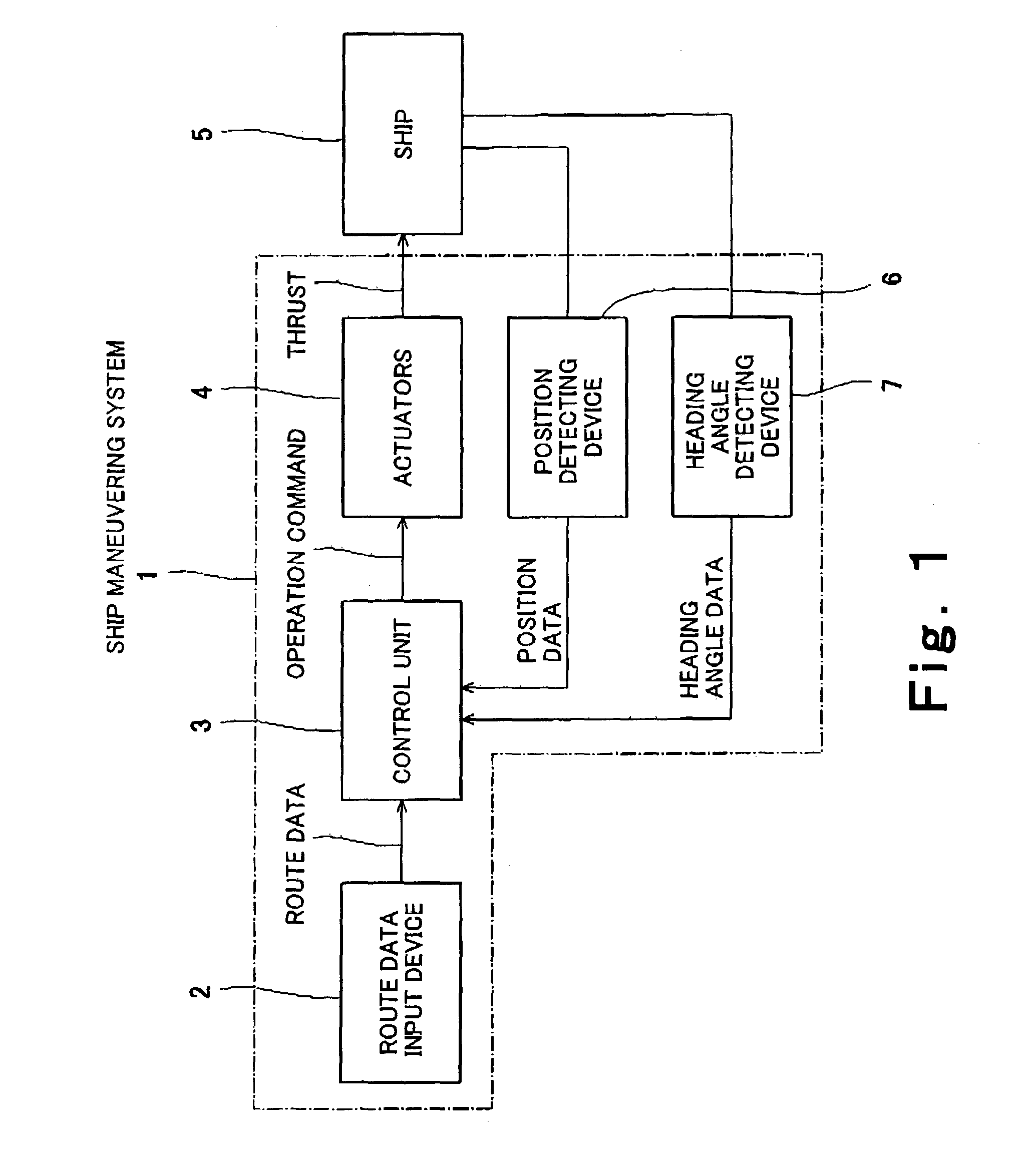
[0063]FIG. 1 is a block diagram showing a structure of a control system of a movable object maneuver system according to a first embodiment of the invention.

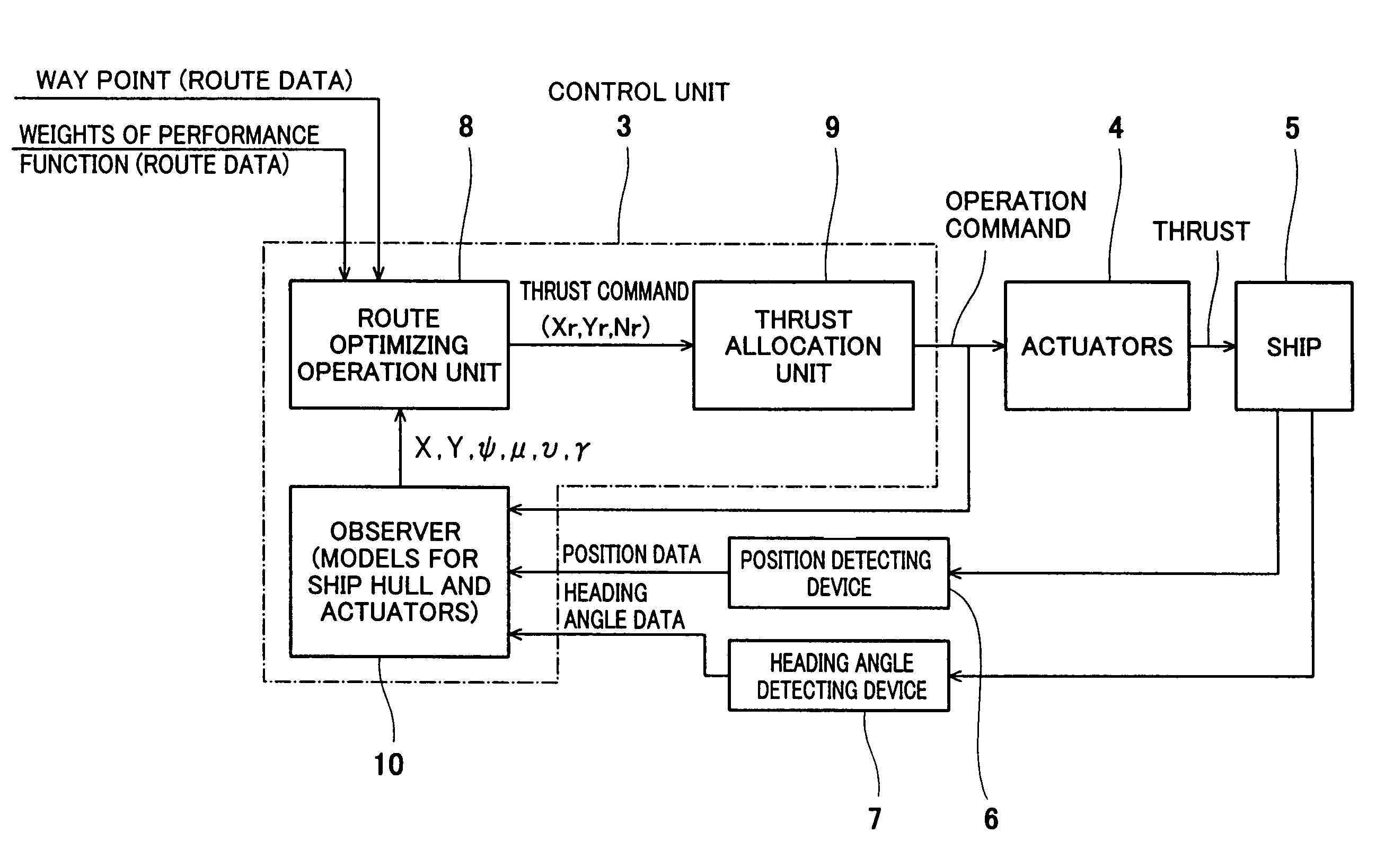
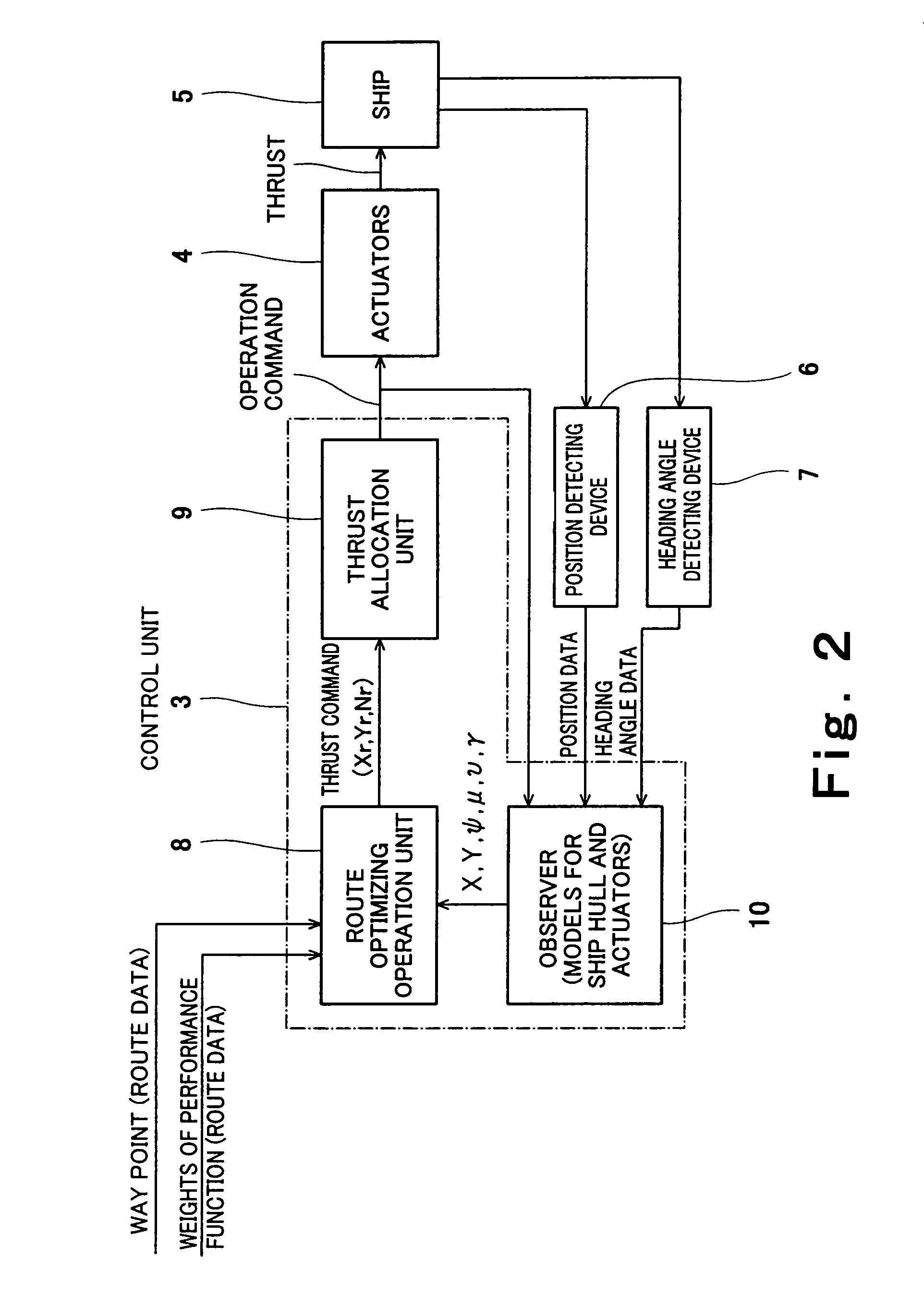
[0064]FIG. 2 is a block diagram showing a structure of the control unit shown in FIG. 1. FIG. 3 diagrammatically shows a layout of individual actuators.

[0065]Referring to FIG. 1, a ship maneuver system 1 exemplifies the movable object maneuver system in the present embodiment. In this embodiment, the movable object is a ship 5. The ship maneuver system 1 has a route data input device 2, a control unit 3, actuators 4, a position detecting device 6, and an heading angle detecting device 7.

[0066]The position detecting device 6 is constituted, for instance, by a GPS (Global Positioning System) and measures the position of the ship 5 to output as positional data. The heading angle detecting device 7 is constituted, for instance, by a gyro compass and measures the heading of the ship 5 to output as data. The route data input device 2 ...

example 1

[0097]FIG. 9 shows a simulation result associated with Example 1. In FIG. 9, the abscissa represents the x coordinate whereas the ordinate represents the y coordinate. Thick lines represent the target position and target heading angle of the ship 5 at the way points WP0 and WP1, respectively. While the ship 5 moves from the way point WP0 to the way point WP1 (with its position changing), the heading angle of the ship 5 changes from the heading angle at the way point WP0 to the heading angle at the way point WP1.

[0098]Where the optimizing control is performed by use of a performance index in which each term is weighed like the equations (1) and (3), if the weights are increased, the performance index increases with the increase in the weights, so that the state of the ship does not become close to the zone where the weights increase. In this example, the weights for the position and heading angle of the ship 5 are set to increase, but the constraint level for them is set to “Loose” (...

example 2

[0099]FIG. 10 shows a simulation result associated with Example 2. In FIG. 10, the abscissa represents the x coordinate whereas the ordinate represents the y coordinate, In this example, the constraint level with respect to the position of the ship is set to “Strict” (extremely great: see FIG. 7), the constraint level with respect to the heading angle of the ship is set to “Loose” (small). Accordingly, the ship 5 substantially sails on the route 101, moving from the way point WP0 to the way point WP1.


PUM


Abstract

A movable object maneuver method wherein a destination point is set; wherein a thrust value is calculated in real time which minimizes or maximizes a performance index associated with one or more state variables and thrust required for a movable object to reach the destination point and which takes into account non-linear conditions inherent to the movable object; and wherein the movable object is moved based on the calculated thrust value.

Description

BACKGROUND OF THE INVENTION[0001]1. Field of the Invention[0002]The present invention relates to a method and system for maneuvering a movable object and more particularly to a method and system for automatically track-keeping a movable object so as to move along a planned route.[0003]2. Related Background Art[0004]One known example of automatic movable object maneuver methods is a marine track-keeping method. For instance, Japanese Patent Publication Kokai Gazette No. 2001-287697 discloses an track-keeping method. This track-keeping method is carried out in the following way: a destination point is set at a position a specified distance away from the present location on the planned route; course and heading deviations are calculated from the destination point; and thrust that needs to be output from a plurality of propellers (hereinafter, referred to as “actuators”) is calculated from the calculated deviations. The route is a continuous planned ship course constituted by a pluralit...

Claims


Application Information

Patent Timeline
Patent Type & Authority Patents(United States)
IPC IPC(8): G01C21/28G01C21/00B63H25/04B64C13/18G05D1/02G08G3/00G08G5/00
CPCG05D1/0206
Inventor FUJIMOTO, HIROAKIKOHNO, YUKINOBUHIGASHI, MASAAKIHAMAMATSU, MASANORINAKASHIMA, KENICHISAITO, YASUOOHNISHI, HIROSHI
Owner KAWASAKI HEAVY IND LTD
Why Eureka
Try Eureka