Method and system for measuring flow at patient utilizing differential force sensor

a sensor and differential force technology, applied in the field ofsensor methods and systems, can solve the problems of increasing the risks of multiple manipulation and entry of iv sites, system compliance is too much to accurately measure dynamic flow at very low flow rate, and fluid delivery is not controlled in view of actual flow rate, so as to minimize system compliance and low flow rate

Active Publication Date: 2010-06-24
HONEYWELL INT INC
View PDF9 Cites 4 Cited by
  • Summary
  • Abstract
  • Description
  • Claims
  • Application Information

AI Technical Summary

Benefits of technology

[0010]It is another aspect of the present invention to provide for an improved fluid delivery system for precisely controlling the flow of the fluid into the patient at very low flow rates and to minimize system compliance.

Problems solved by technology

Each manual step in such procedures increases the risks associated with multiple manipulations and entry of IV sites.
The problem associated with such disposable deliverable systems for fluids, however, is that such a systems possesses too much compliance to accurately measure the dynamic flow at very low flow rates.
Furthermore, the utilized sensor must be sterilized after use or disposed, which is very costly.
While such systems reflect improvements in the art, they do not control fluid delivery in view of actual flow rates and the time required for the fluid to enter the patient increases.
In some circumstances, therefore, such systems may require time ability to deliver fluids over a wide range of delivery rates including very low flow rates.
Moreover, conventional manufacturing techniques tend to be expensive and, therefore, are not well suited for use in manufacturing disposable items.

Method used


Image

  • Method and system for measuring flow at patient utilizing differential force sensor
  • Method and system for measuring flow at patient utilizing differential force sensor
  • Method and system for measuring flow at patient utilizing differential force sensor

Examples


Embodiment Construction

[0019]The particular values and configurations discussed in these non-limiting examples can be varied and are cited merely to illustrate at least one embodiment and are not intended to limit the scope thereof.

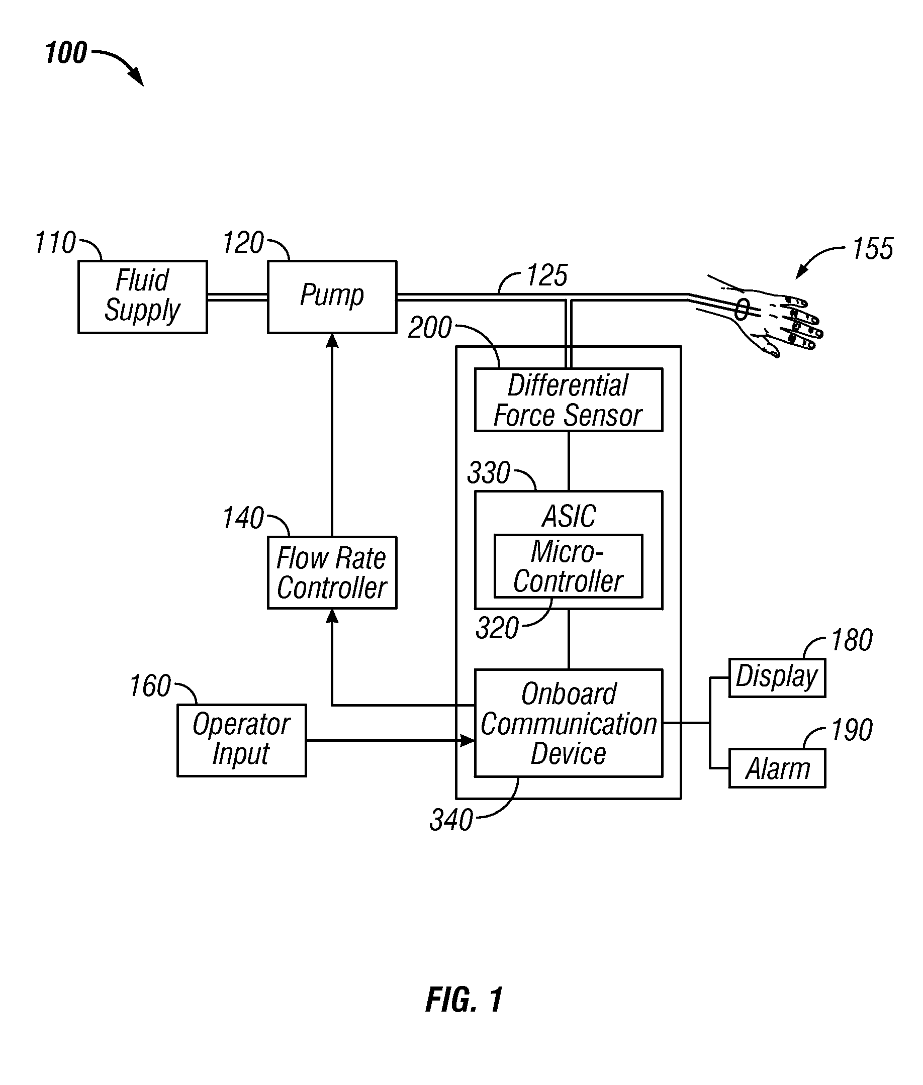
[0020]FIG. 1 illustrates a block diagram of a fluid delivery system 100 that includes a differential force sensor 200, in accordance with a preferred embodiment. The fluid delivery system 100 includes a fluid supply 110 of any desired parenteral fluid and a pump 120, which may be, for example, a peristaltic pump, to which is connected to a tube 125, which in turn is connected to a cannula inserted into the vein of a patient 155. Note that the embodiments discussed herein should not be construed in any limited sense. It can be appreciated that such embodiments reveal details of the structure of a preferred form necessary for a better understanding of the invention and may be subject to change by skilled persons within the scope of the invention without departing from the concept...


PUM


Abstract

A fluid delivery system and method for measuring flow at a patient utilizing a differential force sensor in order to precisely control the flow of fluid at very low flow rates. The system includes a fluid line through which a fluid is conveyed to the patient, and a flow controller that selectively varies a rate of flow of the fluid through the fluid line. The differential force sensor can be mounted very close to a point of entry of the fluid into the patient's body. An onboard communications device is controllably coupled to the flow controller and to the force sensor, responds to an output signal, and provides a feedback to the flow controller in a closed-loop process. The system can pump the fluid at a higher frequency until the flow rate is actually reached at the patient and then adjust to the flow rate needed to ensure patient health.

Description

CROSS-REFERENCE TO PROVISIONAL PATENT APPLICATION[0001]This patent application claims priority to U.S. Provisional Patent Application Ser. No. 61 / 140,295, entitled “Method and System for Measuring Flow at Patient Utilizing Differential Force Sensor,” which was filed on Dec. 23, 2008, and is incorporated herein by reference.TECHNICAL FIELD[0002]Embodiments are generally related to sensor methods and systems. Embodiments are also related to differential force sensors. Embodiments additionally relate to differential force sensors utilized in the context of monitoring manual patient injections through a fluid line.BACKGROUND OF THE INVENTION[0003]A variety of fluid delivery systems have been utilized in the medical field for delivering fluids (e.g., medication, nutrition, saline, etc.) to a patient at relatively precise delivery rates. Such fluid delivery systems include various types of infusion pumps to administer medicinal fluids automatically and over extended periods of time. A typ...

Claims


Application Information

Patent Timeline
Patent Type & Authority Applications(United States)
IPC IPC(8): A61M5/168
CPCA61M5/142A61M5/16804A61M2205/50A61M2205/3362A61M2205/332
Inventor WADE, RICHARD
Owner HONEYWELL INT INC
Why Eureka
Try Eureka