Auxiliary power unit control method and system

Active Publication Date: 2008-05-06
HAMILTON SUNDSTRAND CORP
View PDF32 Cites 50 Cited by
  • Summary
  • Abstract
  • Description
  • Claims
  • Application Information

AI Technical Summary

Benefits of technology

[0007]The present invention is directed to an adjustable APU system and method that allows the APU shaft speed to vary based on the inlet air temperature to the APU compressor. In one embodiment, the APU is controlled by a control law that allows the APU shaft speed to float within a selected range based on speed and electric generator phase matching criteria that

Problems solved by technology

At very low ambient temperatures, the APU compressor and turbine often experience lower efficiencies and narrower compressor flow ranges and consequent compressor/turbine matching problems.
Extremely low temperatures also may cause excessive bleed air pressure.
Although heavier and/or more complex, pneumatic systems may be designed to accommodate the additional pressure, this type of modification is cumbersome and expensive.
Furth

Method used


Image

  • Auxiliary power unit control method and system
  • Auxiliary power unit control method and system
  • Auxiliary power unit control method and system

Examples


Embodiment Construction

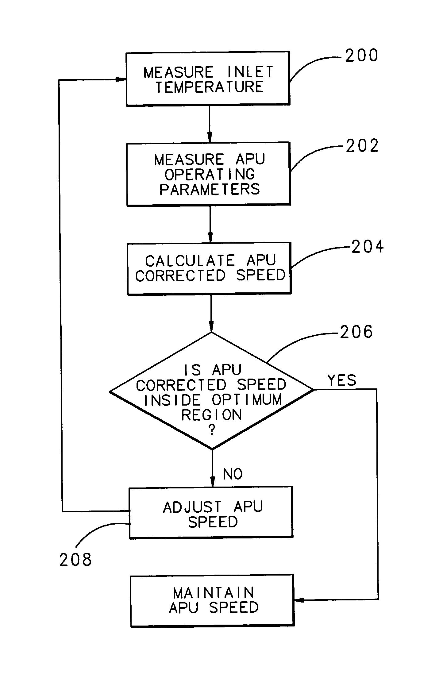
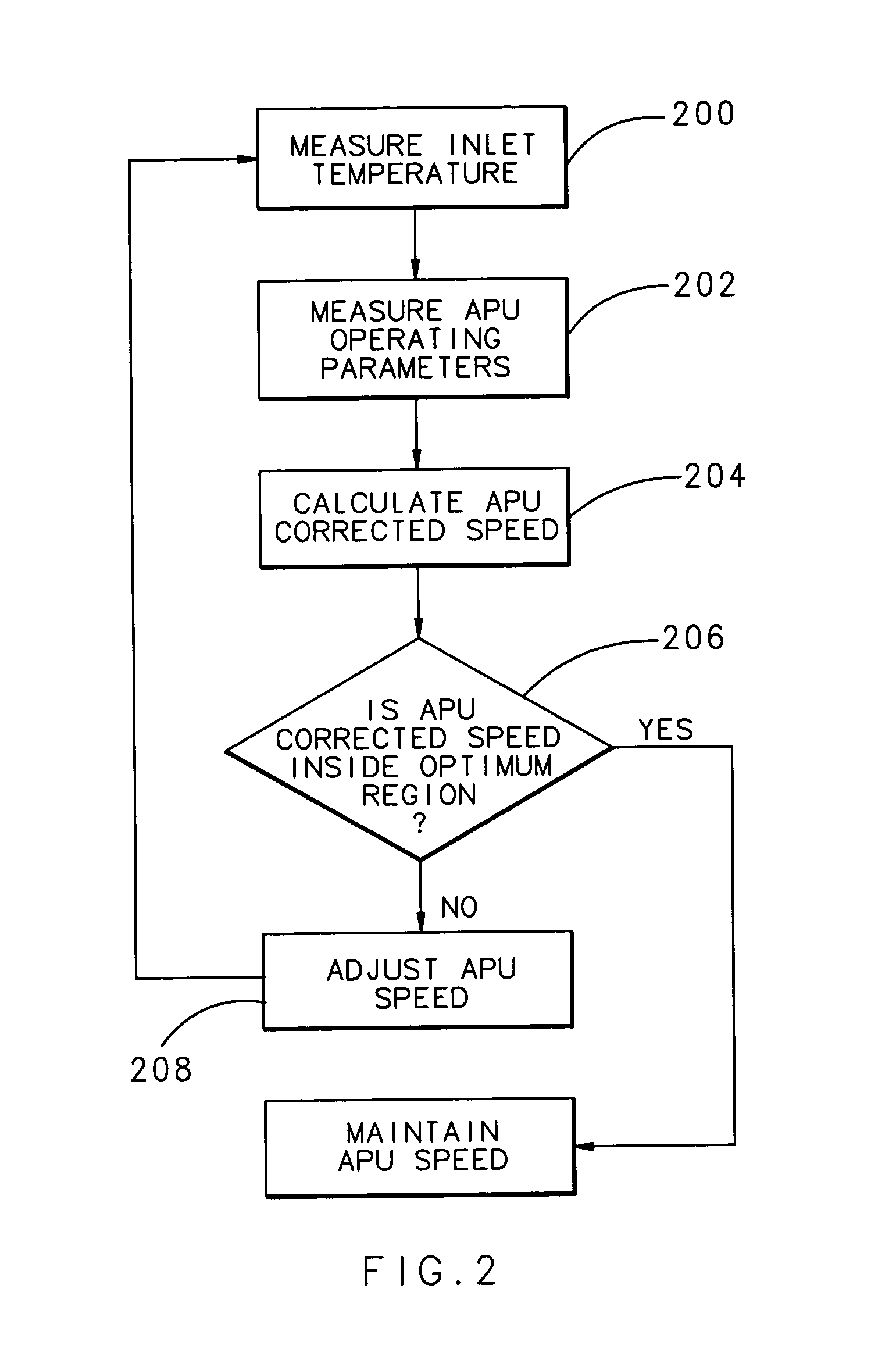
[0013]The present invention is generally directed to a method for varying an auxiliary power unit (APU) compressor performance based on the ambient temperature to optimize APU operation. Allowing the APU shaft speed to vary within a range, such as between 85% and 107% of nominal speed, the invention allows the APU to run faster when the ambient temperature is high and slower when the ambient temperature is low. This range may be overridden to meet selected speed and or phase matching criteria so that or power is transferred smoothly between the APU and other sources of aircraft electric power. Further, some speeds may be prohibited, to maintain a steady acceptable level of stress on the APU components, such as the blades and discs, to prevent undesirable vibratory stress amplification at a mechanical resonance condition. The process itself can be implemented in any known fashion, such as in a processor.

[0014]More particularly, the invention is directed to a method that runs the APU ...


PUM


Abstract

An adjustment method and system for an auxiliary power unit (APU) allows the APU speed to vary based on the inlet air temperature to the APU compressor. The APU is controlled by a control law that allows the APU speed to float within a selected range based on speed and electric power generators phase matching criteria that provides smooth power transfer between the APU and a main engine generator. The specific APU mechanical speed for a given temperature may be determined from a compressor map that identifies the optimum combination of pressure ratio, flow rate and efficiency for a given inlet temperature, and avoids running the APU near mechanical resonant vibration conditions.

Description

TECHNICAL FIELD[0001]The present invention relates to aircraft engine controls, and more particularly to a control for an auxiliary power unit that augments the power of a main aircraft engine.BACKGROUND OF THE INVENTION[0002]Auxiliary power units (APUs) are gas turbine engines often used in aircraft systems to provide pneumatic and shaft power in addition to a main propulsion engine. As is known in the art, a compressor in the APU pumps air into a combustor at a given engine cycle maximum pressure (i.e., some multiple of ambient pressure) so that the combustor burns fuel in a high pressure environment. The burning fuel in the combustor heats the air prior to passing through the turbine. Because the products of combustion expanded through the turbine, above idle fuel flow rate develops more power than needed to drive the cycle compressor, some air (referred to as “bleed air”) can be drawn off and used as a pneumatic output for other aircraft devices. Excess shaft rotational speed on...

Claims


Application Information

Patent Timeline
IPC IPC(8): F02C9/28
CPCF02C9/28F05D2220/50F05D2270/02F05D2270/303
Inventor THOMPSON, ROBERT G.
Owner HAMILTON SUNDSTRAND CORP
Why Eureka
Try Eureka