
Implantable pump with adjustable flow rate

a technology of variable flow rate and pump, which is applied in the direction of engine diaphragms, diaphragm valves, instruments, etc., can solve the problems of limited number of pumps, inefficient pumps, and limited life of variable flow rate pumps

Active Publication Date: 2008-05-06
CODMAN & SHURTLEFF INC
View PDF18 Cites 70 Cited by
  • Summary
  • Abstract
  • Description
  • Claims
  • Application Information

AI Technical Summary

Benefits of technology

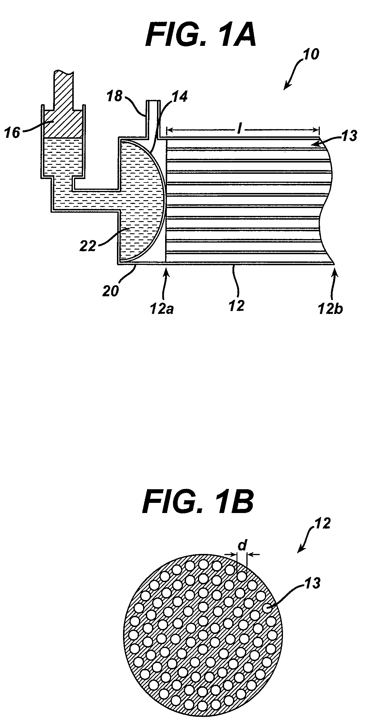
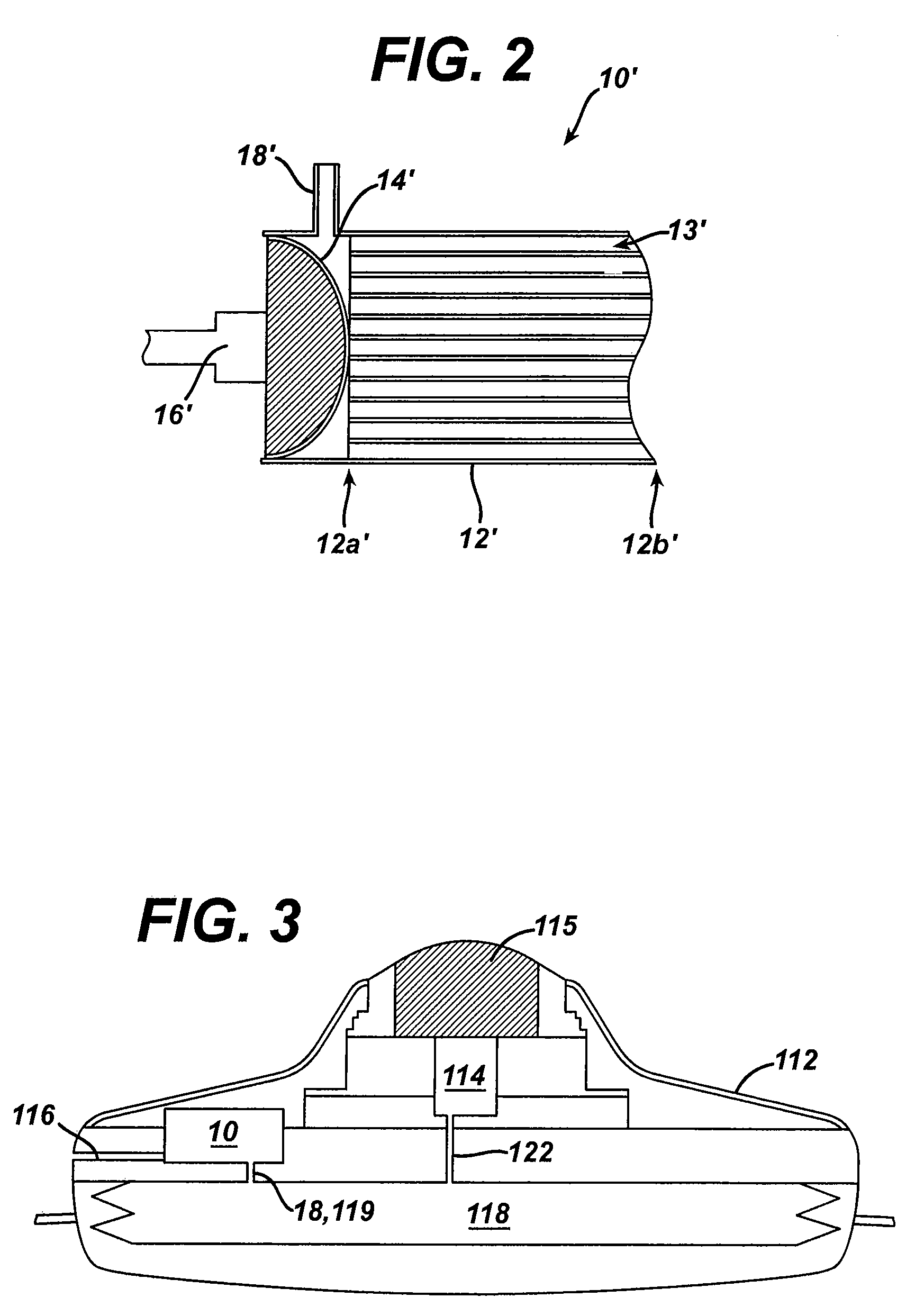
"The present invention provides a valve that can control the flow rate of fluid from an implantable pump. This valve includes a multi-lumen member and a restrictor member that can selectively restrict at least a portion of the lumens in the member to adjust the flow rate. The valve can be actuated by a mechanical or electromechanical member and can be disposed within the housing of the pump or within a fluid delivery catheter. The invention also provides an implantable drug-delivery pump with the valve and an orifice for measuring the flow rate of fluid. The methods for controlling the flow rate of fluid being delivered to a patient from an implantable pump are also provided."

Problems solved by technology

While these pumps provide some advantages over fixed flow rate pumps, the use of such pumps has some drawbacks.
In particular, variable flow rate pumps have a normal life that is limited by the life of the battery.
Since these pumps require an active pumping mechanism or an active valve to control flow rate, the pumps tend to be inefficient as they consume energy to operate the pump.
Further, in order to guard against the shortening of the device's useful life, variable flow rate pumps are typically not manufactured with additional power-consuming features such as sensors and other diagnostic equipment which would provide useful for monitoring the patient during treatment.
One other problem associated with current variable flow rate pumps is that they only allow for a limited number of pre-set flow rates.

Method used


Image

  • Implantable pump with adjustable flow rate
  • Implantable pump with adjustable flow rate
  • Implantable pump with adjustable flow rate

Examples


Embodiment Construction

[0021]The present invention generally provides a valve that is adapted to control the flow rate of fluid flow from an implantable pump or another fluid delivery device. In general, the valve includes a multi-lumen member that is adapted to receive fluid-flow therethrough, and a restrictor member that is coupled to the multi-lumen member such that the restrictor member is effective to selectively restrict at least a portion of one or more lumens in the multi-lumen member to thereby adjust the flow rate of fluid flowing through the multi-lumen member. The valve can be built into an implantable drug pump to control fluid flow exiting the pump, or alternatively the valve can disposed within a catheter or otherwise coupled to an outlet port in an implantable drug pump to control the flow rate of fluid exiting the drug pump.

[0022]The device is particularly advantageous in that it allows the flow rate to be set to a desired flow rate within a broad continuum of flow rates, unlike prior art...


PUM


Abstract

A valve that is adapted to control the flow rate of fluid flow from an implantable pump or other fluid delivery device is provided. In general, the valve includes a multi-lumen member that is adapted to receive fluid-flow therethrough, and a restrictor member that is coupled to the multi-lumen member such that the restrictor member is effective to selectively restrict at least a portion of one or more lumens in the multi-lumen member to thereby adjust the flow rate of fluid flowing through the multi-lumen member. The valve can be built into an implantable drug pump to control fluid flow exiting the pump, or alternatively the valve can disposed within a catheter or otherwise coupled to an outlet port in an implantable drug pump to control the flow rate of fluid exiting the drug pump.

Description

FIELD OF THE INVENTION[0001]The present invention relates to an implantable pump having a continuous fluid flow with an adjustable flow rate.BACKGROUND OF THE INVENTION[0002]Implantable drug delivery devices are commonly used to provide site specific and / or sustained delivery of beneficial agents to address adverse patient conditions. The pumps are used for the continuous medication delivery over relatively long periods of time in patients who could otherwise only be treated by injecting the medications, such as, e.g., morphines, heparins and similar drugs, several times daily. Pumps are advantageous in comparison with injections in that an even flow rate and a significantly lower total intake of the drug can be realized.[0003]Implantable drug pumps typically include a reservoir for storing a fluid, such as a drug, and a pump or other flow control device to deliver the fluid to a site within a patient. A septum is formed on the top of the pump to allow refilling of the reservoir. Mo...

Claims


Application Information

Patent Timeline
Patent Type & Authority Patents(United States)
IPC IPC(8): A61K9/22A61M5/14A61M5/142A61M5/168A61M37/00F04B43/06F16K7/17
CPCA61M5/14276A61M39/227F16K7/17A61M5/141A61M5/16813A61M2205/3507
Inventor ROSENBERG, MEIRMACBRIDE, DOUGLAS
Owner CODMAN & SHURTLEFF INC
Learn More