
Optical sensor device having variable optical path length

a technology of optical path length and optical sensor, which is applied in the direction of measurement devices, sampling, instruments, etc., can solve the problems of reducing the maximum measurement range, not keeping pace with the trend, and optical monitoring instrumentation

Active Publication Date: 2008-05-06
FINESSE SOLUTIONS
View PDF3 Cites 36 Cited by
  • Summary
  • Abstract
  • Description
  • Claims
  • Application Information

AI Technical Summary

Problems solved by technology

However, optical monitoring instrumentation, which is an integral part of nearly every production process in the biotechnology industry, has not kept pace with this trend.
Increasing the OPL improves sensitivity but reduces the maximum measurement range.
One of the drawbacks of current UV sensors is that even minor OPL changes require time-consuming and sometimes expensive hardware changes.
More importantly, if the specific required flow cells are unavailable from a vendor or other supplier, this switch can delay processing for 4-6 weeks or other significant amount of time.
Maintaining this inventory also has additional associated costs based on the requirement of traceability of materials.
Existing UV sensors also have significant drawbacks in precision / accuracy.
This means that a cumulative error of ±0.15 mm is still within tolerance.
Probably the most common optical path length for chromatography applications is 1 mm, which means that the stated tolerances could result in an error of ±15%.
These deviations are impractical in situations where a precise determination of OPL is desirable.
This makes it difficult, if not impossible, to determine the actual OPL of an installed UV sensor without removing the flow cell from the process, and in many cases, completely disassembling it.
This problem has led to many instances of faulty calibration based on incorrect assumptions about optical path length.
Also, because the windows for different optical path length are identical in appearance except for small variations in length (sometimes as small as 0.5 mm, for instance), it is extremely easy for users to mismatch windows when re-assembling flow cells after cleaning or service, again resulting in incorrect OPLs.
Since there is no external indication of optical path length, this type of problem can take many hours to resolve.
In the worst-case scenario, the manufacturer actually makes product using the improperly configured sensor to control cuts.
Other costs are associated with current UV sensors having fixed OPLs.
For instance, there is also the additional cost of bringing the UV sensor back into a clean environment and re-sterilizing after an OPL change has been made.
Clearly therefore, current UV sensors having fixed OPLs are impractical in many situations.

Method used


Image

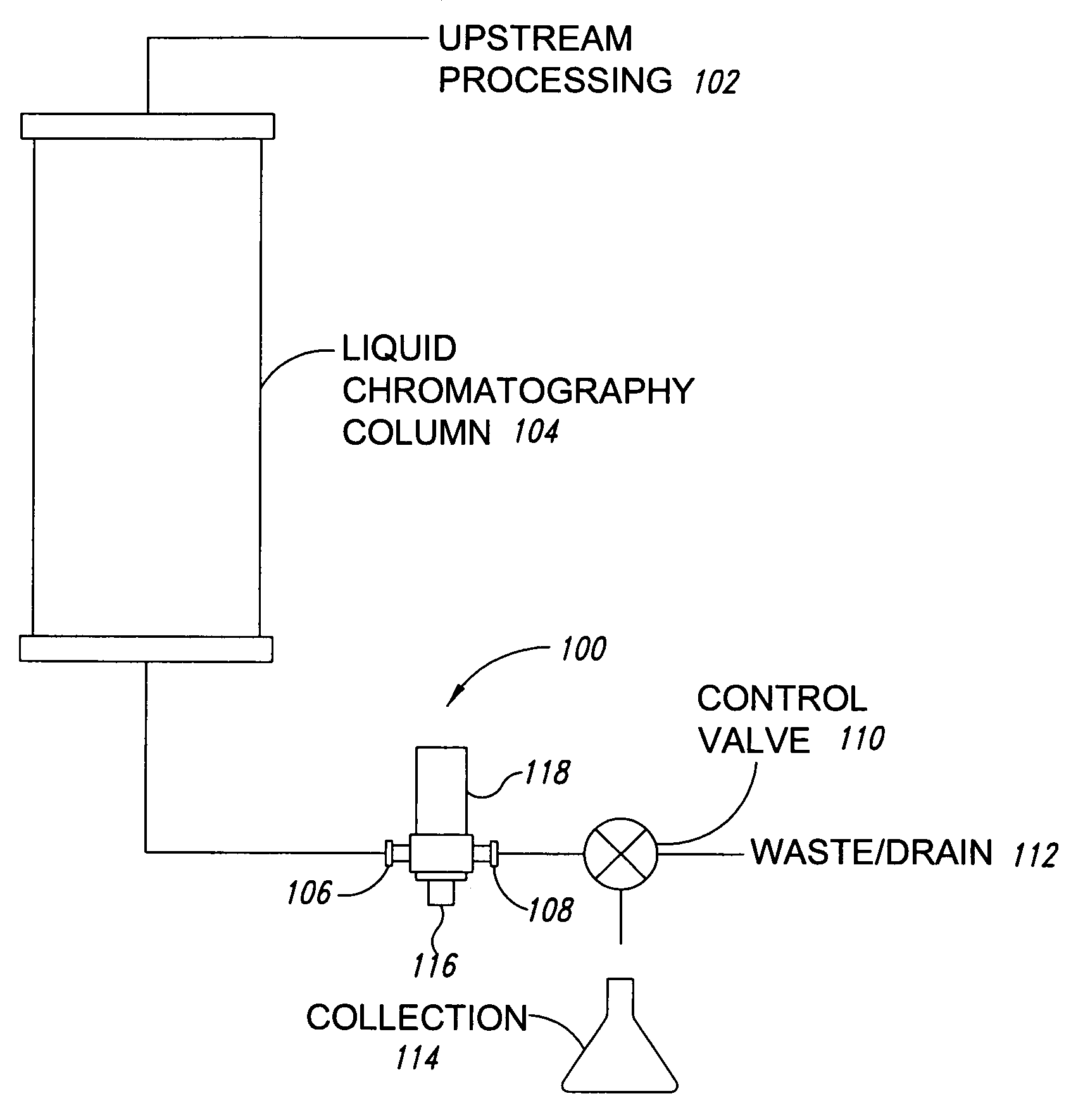
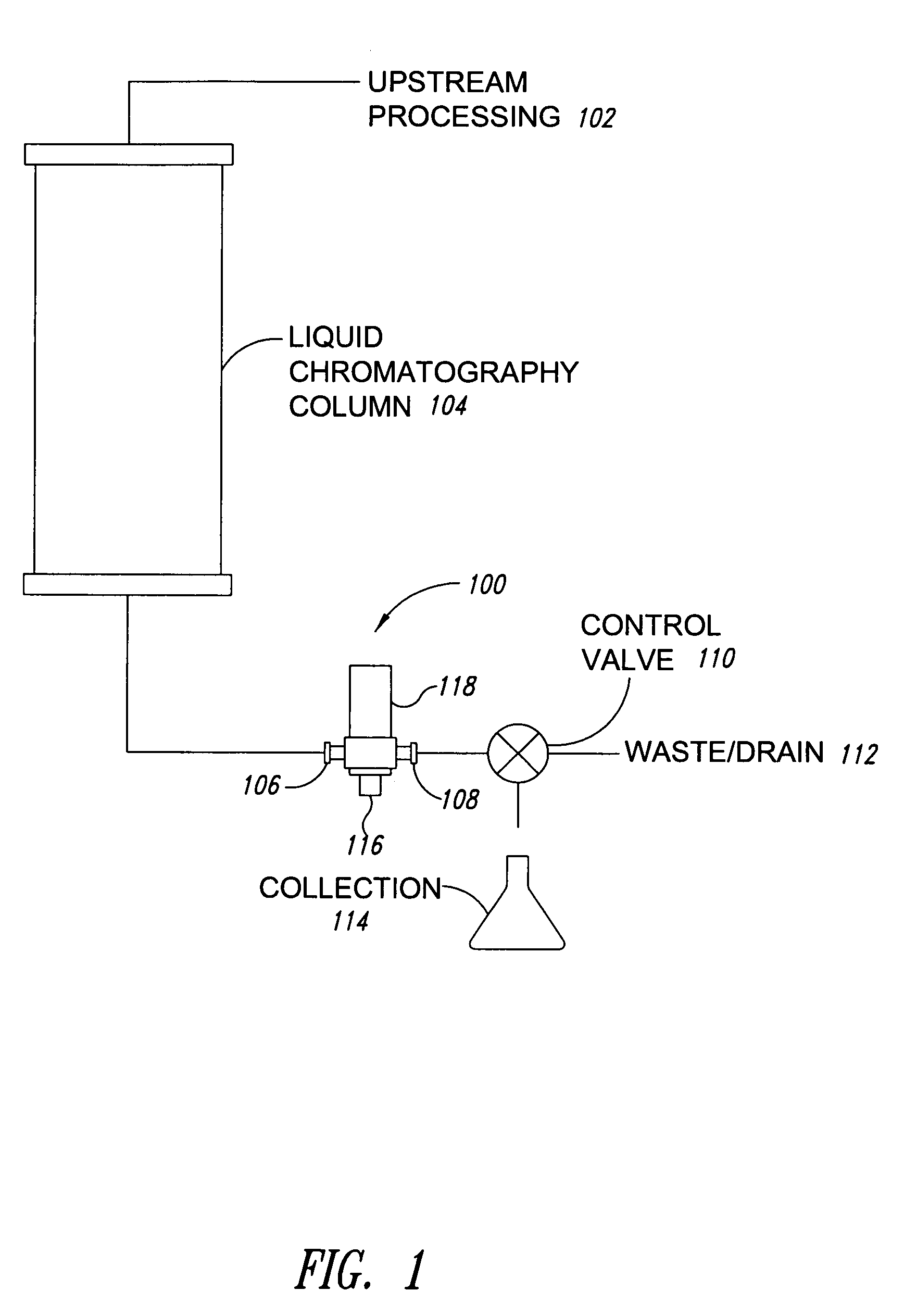
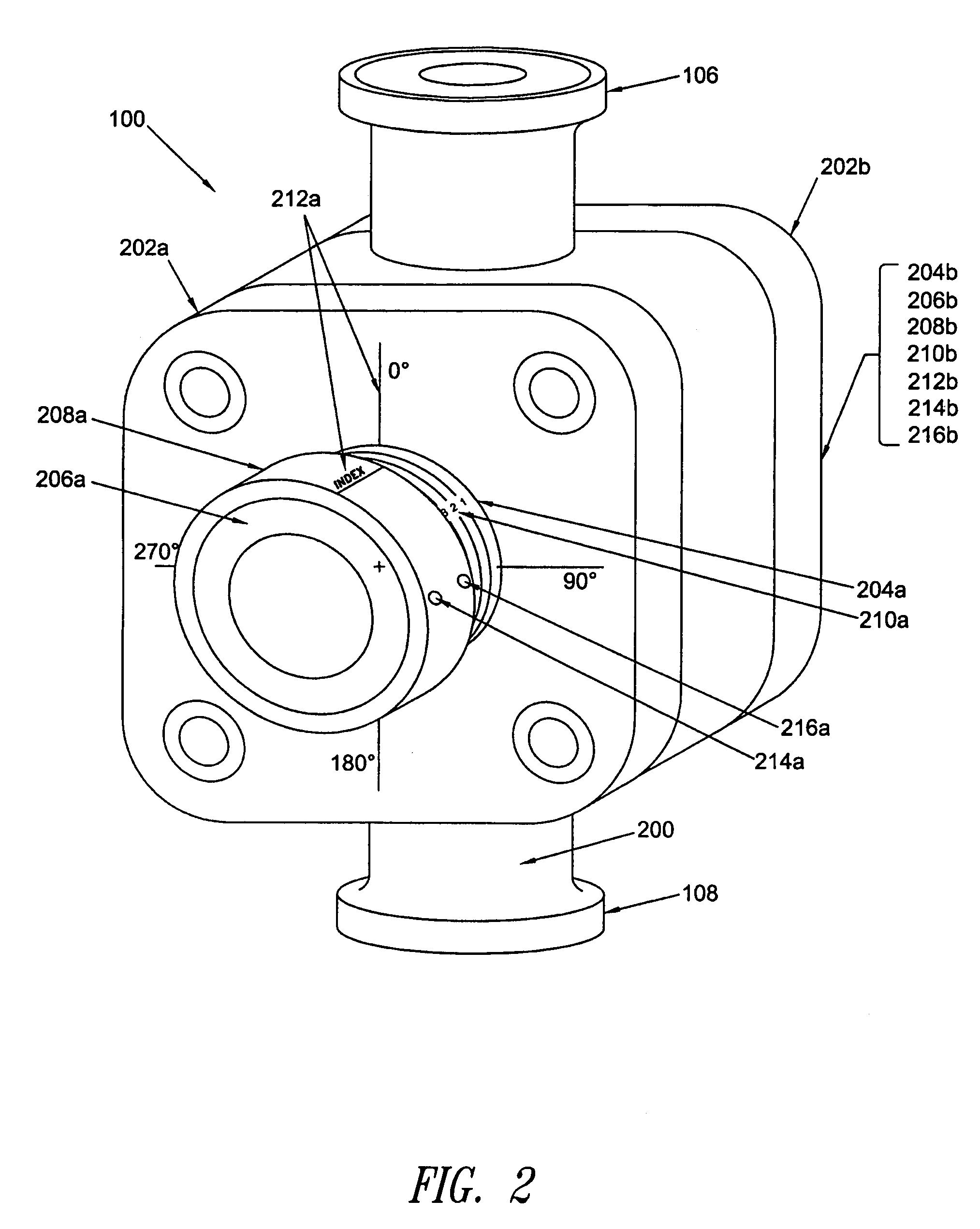
  • Optical sensor device having variable optical path length
  • Optical sensor device having variable optical path length
  • Optical sensor device having variable optical path length

Examples


Embodiment Construction

[0019]In the following description, numerous specific details are given to provide a thorough understanding of embodiments. One skilled in the relevant art will recognize, however, that the invention can be practiced without one or more of the specific details, or with other methods, components, materials, etc. In other instances, well-known structures, materials, or operations are not shown or described in detail to avoid obscuring aspects of the invention.

[0020]Reference throughout this specification to “one embodiment” or “an embodiment” means that a particular feature, structure, or characteristic described in connection with the embodiment is included in at least one embodiment. Thus, the appearances of the phrases “in one embodiment” or “in an embodiment” in various places throughout this specification are not necessarily all referring to the same embodiment. Furthermore, the particular features, structures, or characteristics may be combined in any suitable manner in one or m...


PUM


Abstract

An optical sensor is provided with an adjustable and variable optical path length (OPL). The optical sensor can be used in conjunction with a flow cell for ultraviolet (UV) absorbance measurements. On opposite sides of the flow cell, optical windows are installed in cylindrical window holders and held in place by window retainers. The distance between opposing faces of the optical windows defines the OPL. A fine pitch, close tolerance thread is machined on the outside of the window holders. This thread mates with a thread machined on an inside wall of a mounting ring. Rotation of the window holder and attached optics housing extends or retracts the window and window holder assembly, thereby providing the variable OPL. The OPL can be ascertained by examining external visual linear and / or rotational indicators on the sensor device.

Description

TECHNICAL FIELD[0001]This disclosure relates generally to optical sensor devices, and in particular but not exclusively, relates to an optical monitoring device, such as an inline flow cell device usable for ultraviolet (UV) absorbance measurements and having an adjustable optical path length.BACKGROUND INFORMATION[0002]The biotechnology industry has progressed over the years from relatively simple lab benches to highly complex manufacturing processes. The industry has adopted manufacturing techniques and equipment from various existing processes and modified such processes to meet certain distinct uses. For example, in-line optical monitoring instrumentation (originally developed for applications ranging from brewing to chemical process) has been modified for use in the biotechnology field.[0003]The biotechnology industry has evolved considerably with the development of new processing equipment and techniques to improve yields, ensure regulatory compliance, and increase production ...

Claims


Application Information

Patent Timeline
IPC IPC(8): G01N21/01
CPCG01N21/0303G01N21/05
Inventor HEWITT, JOSEPH P.
Owner FINESSE SOLUTIONS
Learn More