
Electronically tunable quad-band antennas for handset applications

a quad-band antenna, electromagnetic technology, applied in the field of antennas, can solve the problems of not always being able to achieve without utilizing sophisticated and expensive antennas, and the problem of affecting the use of expensive and sophisticated antennas with consumer handsets

Active Publication Date: 2008-05-06
NXP USA INC
View PDF32 Cites 62 Cited by
  • Summary
  • Abstract
  • Description
  • Claims
  • Application Information

AI Technical Summary

Benefits of technology

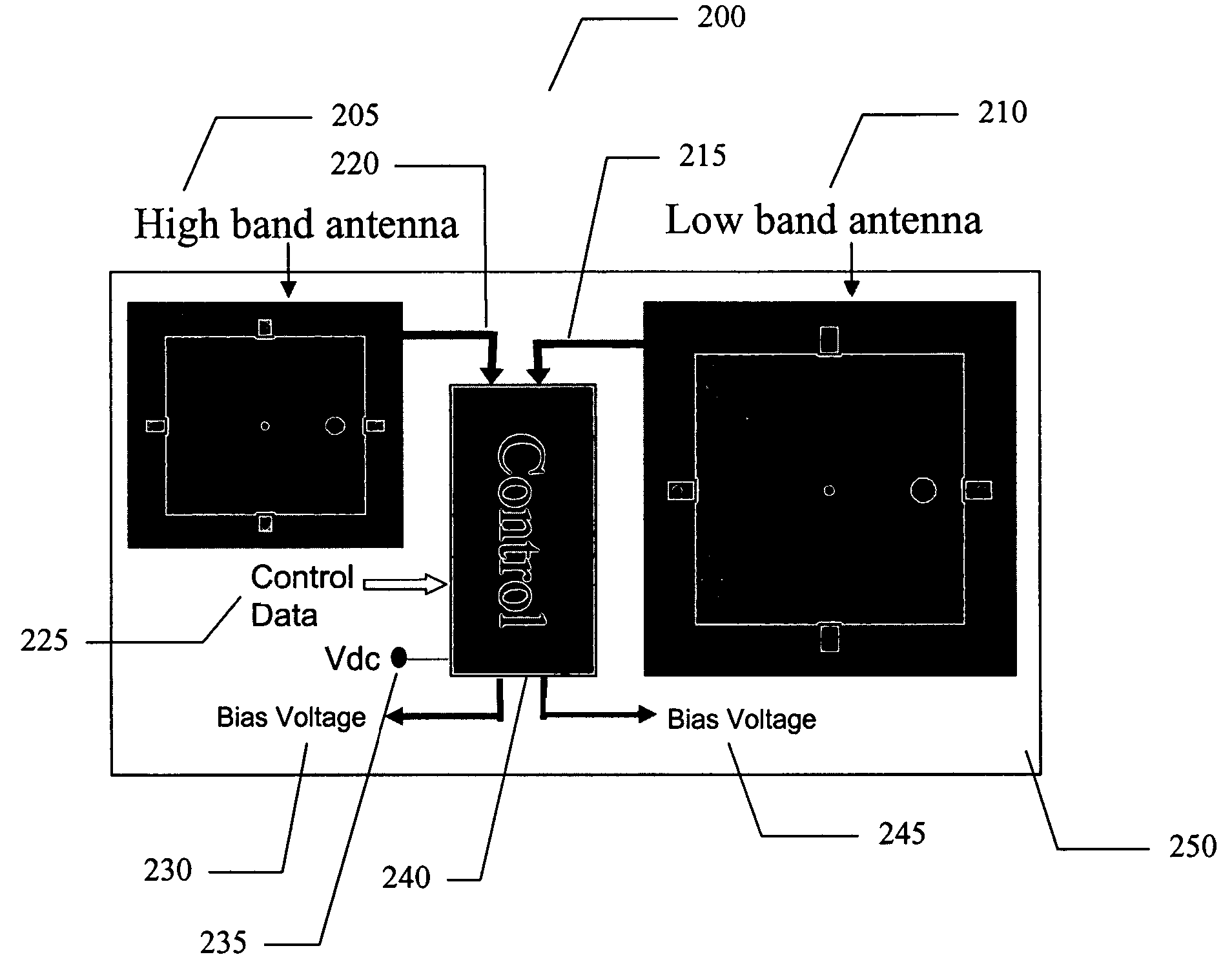
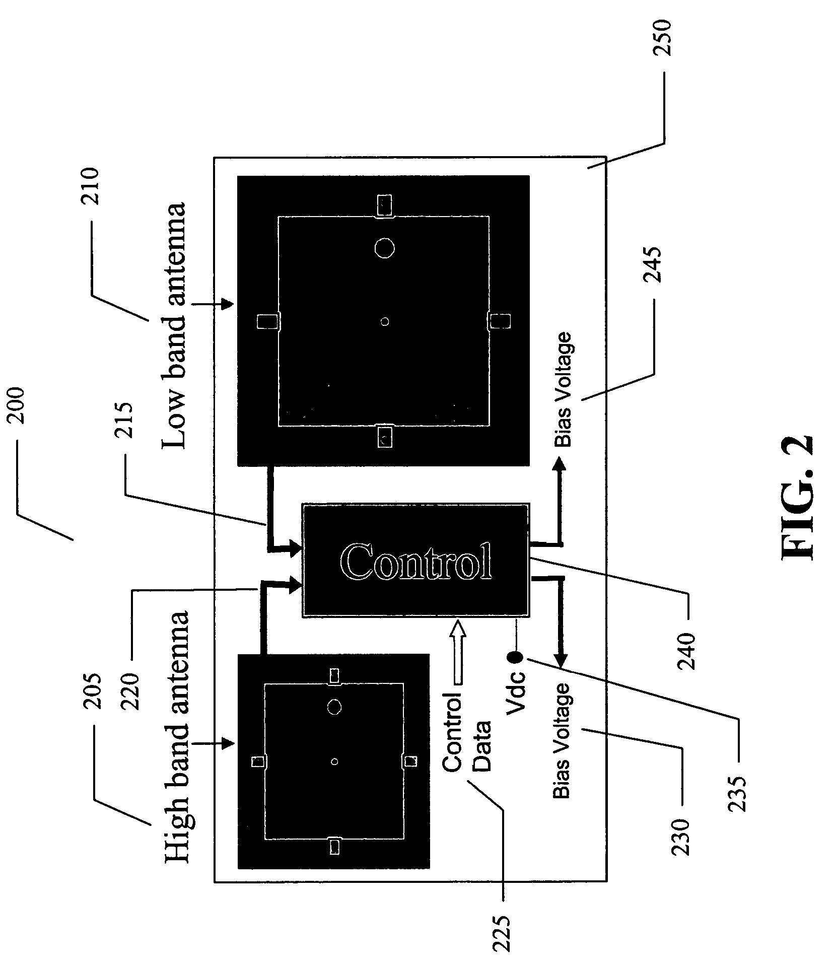
The present invention provides an electronically tunable quad-band antenna that can be used to transmit and receive RF signals from multiple frequency bands. The antenna includes a tunable high band antenna and a tunable low band antenna, each with its own voltage tunable varactor. The antenna also includes a controller that can control the bias voltage for each varactor to tune the antenna for different RF input frequencies and temperatures. The antenna covers the following frequency bands and standards: 824-894 MHz, 880-960 MHz, 1710-1880 MHz, 1850-1990 Hz, GSM850, EGSM, GSM1800, and PCS 1900. The invention allows for efficient and flexible RF signal transmission and reception in multiple frequency bands.

Problems solved by technology

This may not always be achievable without utilizing sophisticated and expensive antennas.
Using expensive and sophisticated antennas with consumer handsets is problematic.

Method used


Image

  • Electronically tunable quad-band antennas for handset applications
  • Electronically tunable quad-band antennas for handset applications
  • Electronically tunable quad-band antennas for handset applications

Examples


Embodiment Construction

[0025]The present invention provides electronically tunable antennas used in multi-band, multi-mode mobile phones applications. The preferred tuning elements are voltage-controlled tunable dielectric capacitors placed on the antenna package. The present technology makes tunable antennas very promising in the contemporary mobile communication system applications. Thus, it is an object of the present invention to provide a tunable antenna for Handset applications, which, in a preferred embodiment consists of two tunable antennas in the same package. The first antenna covers the low band (824-960 MHz), and the second antenna covers the high band (1710-1990 MHz). Both of the antennas need to provide a good match to the transmit and receive modules over more than 15% of their frequency bands. In typical architectures, this would not always be achievable without going to sophisticated and expensive antennas. However, this problem can easily be solved by using an electronically tunable ant...


PUM


Abstract

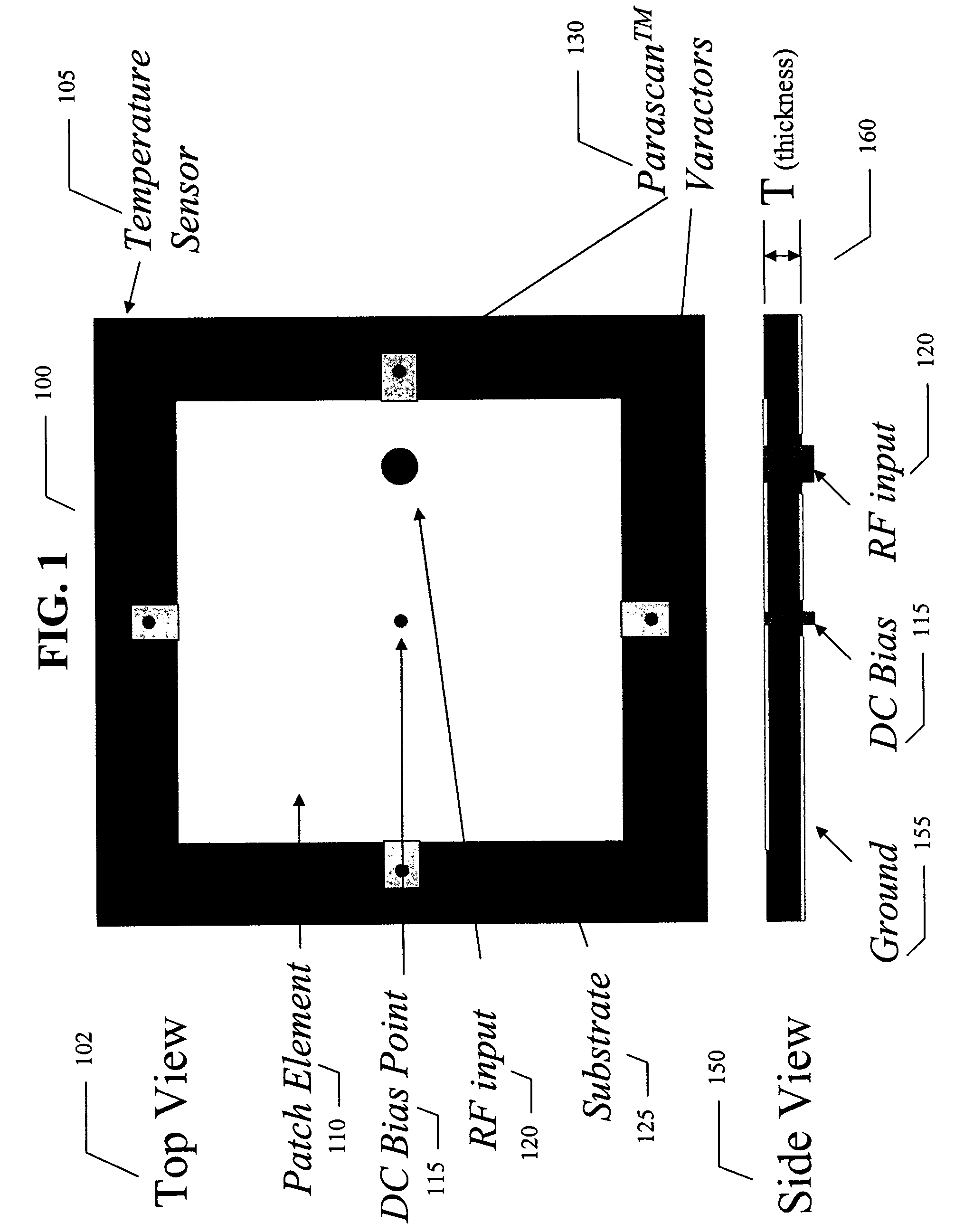
An electronically tunable quad-band antenna which includes a tunable high band antenna tuned by at least one tunable varactor associated therewith; the tunable high band antenna further includes a substrate, a patch element on said substrate, at least one voltage tunable varactor associated with the patch element, a DC bias point on the patch element, an RF input on the patch element, and a temperature sensor associated with the high band pass antenna. Also included in a preferred embodiment of the electronically tunable quad-band antenna of the present invention is a tunable low band antenna tuned by at least one tunable varactor associated therewith, the tunable low band antenna further including a substrate, a patch element on said substrate, at least one voltage tunable varactor associated with said patch element, a DC bias point on said patch element, an RF input on said patch element, and a temperature sensor associated with said low band pass antenna.Also included is a controller receiving control data, and receiving output information from said low band antenna and output information from said high band antenna and controlling a first bias voltage for biasing the at least one voltage tunable varactor associated with the high band antenna and a second bias voltage for biasing the at least one voltage tunable varactor associated with the low band antenna. The bias voltages can be provided by a DC to DC converter regulator.

Description

CROSS-REFERENCE TO RELATED APPLICATION[0001]This application claims priority to U.S. Provisional Patent Application Ser. No. 60 / 445,348, “ELECTRONICALLY TUNABLE QUAD-BAND ANTENNAS FOR HANDSET APPLICATIONS” filed Feb. 5, 2003, by Khosro Shamsaifar.BACKGROUND OF THE INVENTION[0002]The present invention relates generally antennas and more specifically to tunable antennas and still more specifically to tunable quad-band antennas for handset applications.[0003]The current trend in mobile communications is in providing more and better services to the subscribers. Modern multi-mode, multi-band mobile phones will give better coverage and provide more data rates. This puts very stringent requirements on the components of the transceivers, including the antennas, which must handle these new features.[0004]A Quad-Band handset radio transceiver is an example of a multi-mode, multi-band system. It covers the following frequency bands and standards:[0005]824-894 MHz;[0006]880-960 MHz;[0007]1710-1...

Claims


Application Information

Patent Timeline
Patent Type & Authority Patents(United States)
IPC IPC(8): H04B1/26H01Q1/00H01Q1/24H01Q5/00H01Q9/04H01Q11/12H01Q21/29H01Q21/30H01Q23/00H04B1/04H04B1/18H04B1/40
CPCH01Q1/243H01Q9/0407H01Q9/0442H01Q9/14H01Q21/29H01Q21/30H01Q23/00
Inventor SHAMSAIFAR, KHOSRO
Owner NXP USA INC
Learn More