
Approach to minimize worst-case queuing delay for a switching communication system with transmission constraints

a communication system and transmission constraint technology, applied in the field of communication systems, can solve the problems of reducing application response times, putting tremendous strain on network resources (e.g., switch capacity), and less tolerant of network delays, so as to minimize the output delay, and minimize the queueing delay of packets

Inactive Publication Date: 2008-05-06
U S BANK NAT ASSOC
View PDF31 Cites 57 Cited by
  • Summary
  • Abstract
  • Description
  • Claims
  • Application Information

AI Technical Summary

Benefits of technology

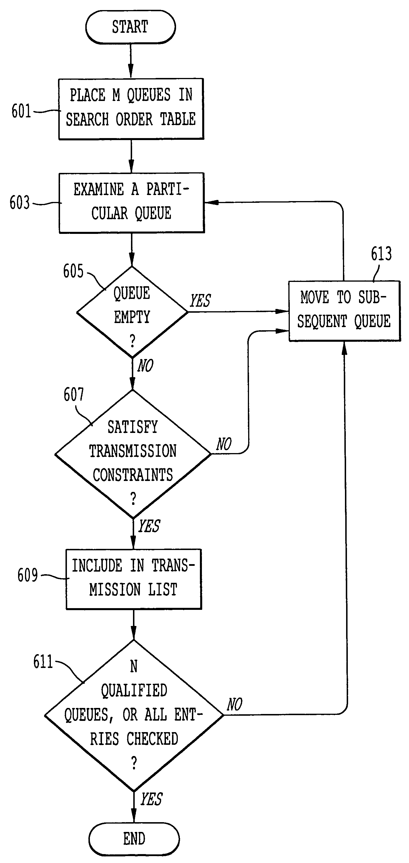
[0012]According to one aspect of the invention, a method is provided for minimizing queueing delay of packets in a communication system. The method includes retrieving a search order table that has a plurality of table entries corresponding to M queues that selectively store the packets. The table entries store values that correspond to the relative positions of the M queues and that are selected based upon a transmission constraint of the communication system. The method also includes scheduling transmission of the packets that are stored in the M queues based upon the search order table. Under this approach, the output delay is minimized, and the upper bound is known.
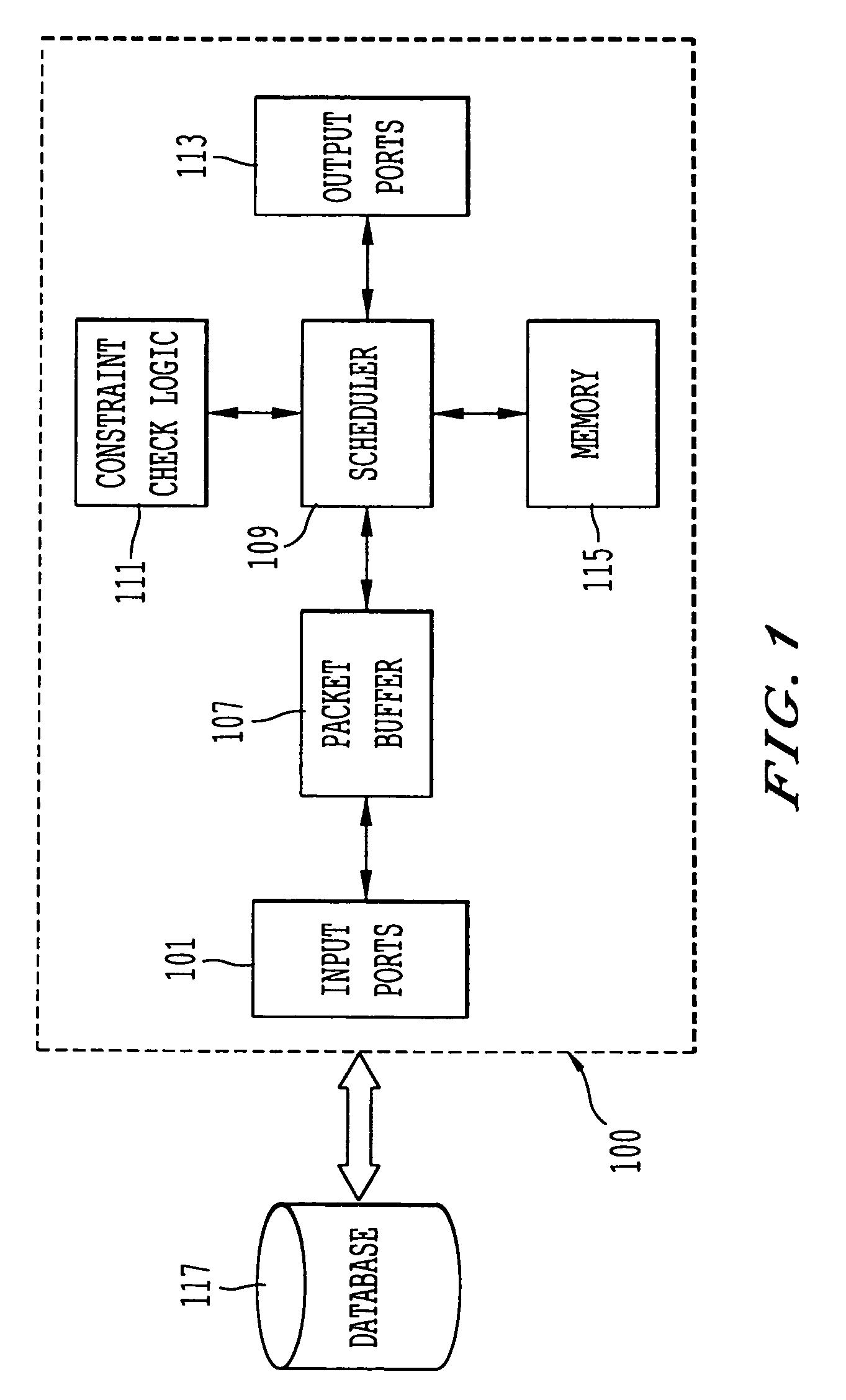
[0013]According to another aspect of the invention, a communication system for minimizing queueing delay of packets comprises M queues that are configured to store the packets. A memory stores a search order table that has a plurality of table entries corresponding to the M queues. The table entries store values that correspond to relative positions of the M queues and that are selected based upon a transmission constraint of the communication system. A scheduler is coupled to the memory and is configured to schedule transmission of the packets stored in the M queues based upon the search order table. The above arrangement controls queueing delays and provides fair servicing of the queues.
[0014]According to another aspect of the invention, a switching device comprises a plurality of input ports. Each of the input ports is configured to receive a plurality of packets. A plurality of queues are configured to store the plurality of packets. A memory stores a search order table that has a plurality of table entries. The table entries store values that correspond to relative positions of the plurality of queues and that are selected based upon a transmission constraint, wherein the number of queues is M. A scheduler is coupled to the memory and configured to schedule transmission of the packets stored in the queues based upon the search order table. A plurality of output ports are configured to transmit the stored packets in the plurality of queues based upon the transmission constraint, wherein the stored packets in N number of M queues are selected for transmission. Under this arrangement, the worst-case queueing delay can be minimized, and the upper-bound can be computed independent of the traffic load and the traffic characteristics.
[0015]In yet another aspect of the invention, a computer-readable medium carrying one or more sequences of one or more instructions for minimizing queueing delay of packets in a communication system is disclosed. The one or more sequences of one or more instructions include instructions which, when executed by one or more processors, cause the one or more processors to perform the step of retrieving a search order table that has a plurality of table entries corresponding to M queues that selectively store the packets. The table entries store values that correspond to relative positions of the M queues and that are selected based upon a transmission constraint of the communication system. Another step includes scheduling transmission of the packets stored in the M queues based upon the search order table. This approach advantageously provides fair servicing of queues.

Problems solved by technology

For example, the maturity of electronic commerce and acceptance of the Internet as a daily tool pose an enormous challenge to communication engineers to develop techniques to reduce network latency and user response times. With the advances in processing power of desktop computers, the average user has grown accustomed to sophisticated multimedia applications, which place tremendous strain on network resources (e.g., switch capacity).
Also, because the decrease in application response times is a direct result of the increased processor performance, the user has grown less tolerant of network delays, demanding comparable improvements in the network infrastructure.
Network latency is attributable, in part, to queueing delays.
Conventionally, queueing delays are difficult to predict or bound, in part, because of the correlation between the output traffic and the input traffic, which can exhibit a wide variety of behaviors (e.g., stochastic, deterministic, or a combination thereof).
As a result of the inability to readily determine an upper bound on the queueing delay, applications cannot efficiently determine a timeout period for retransmitting lost or greatly delayed packets.
Without accurate knowledge of the upper bound, the end users are unable to receive a guarantee on their application response times. To further exacerbate the increased response times, the delays are not uniform across the users; that is, some users, by virtue of the relative position of the queues that store their traffic, may experience significantly more delay than other users.
Thus, the queues are not serviced fairly during network congestion, for example.
The main drawback with this forklift approach is cost.
Further, in some systems, such as a communication satellite, hardware replacement is impractical.

Method used


Image

  • Approach to minimize worst-case queuing delay for a switching communication system with transmission constraints
  • Approach to minimize worst-case queuing delay for a switching communication system with transmission constraints
  • Approach to minimize worst-case queuing delay for a switching communication system with transmission constraints

Examples


Embodiment Construction

[0028]In the following description, for the purpose of explanation, specific details are set forth in order to provide a thorough understanding of the invention. However, it will be apparent that the invention may be practiced without these specific details. In some instances, well-known structures and devices are depicted in block diagram form in order to avoid unnecessarily obscuring the invention.

[0029]The present invention minimizes queueing delay of packets, in which multiple queues are configured to store packets for transmission. A memory stores a search order table that has table entries corresponding to the queues. Specifically, the table entries store values that correspond to the relative positions of the queues and that are selected based upon a transmission constraint of the communication system. A scheduler schedules transmission of the packets that are stored in the queues based upon the search order table. A class of search order tables are generated that satisfy mul...


PUM


Abstract

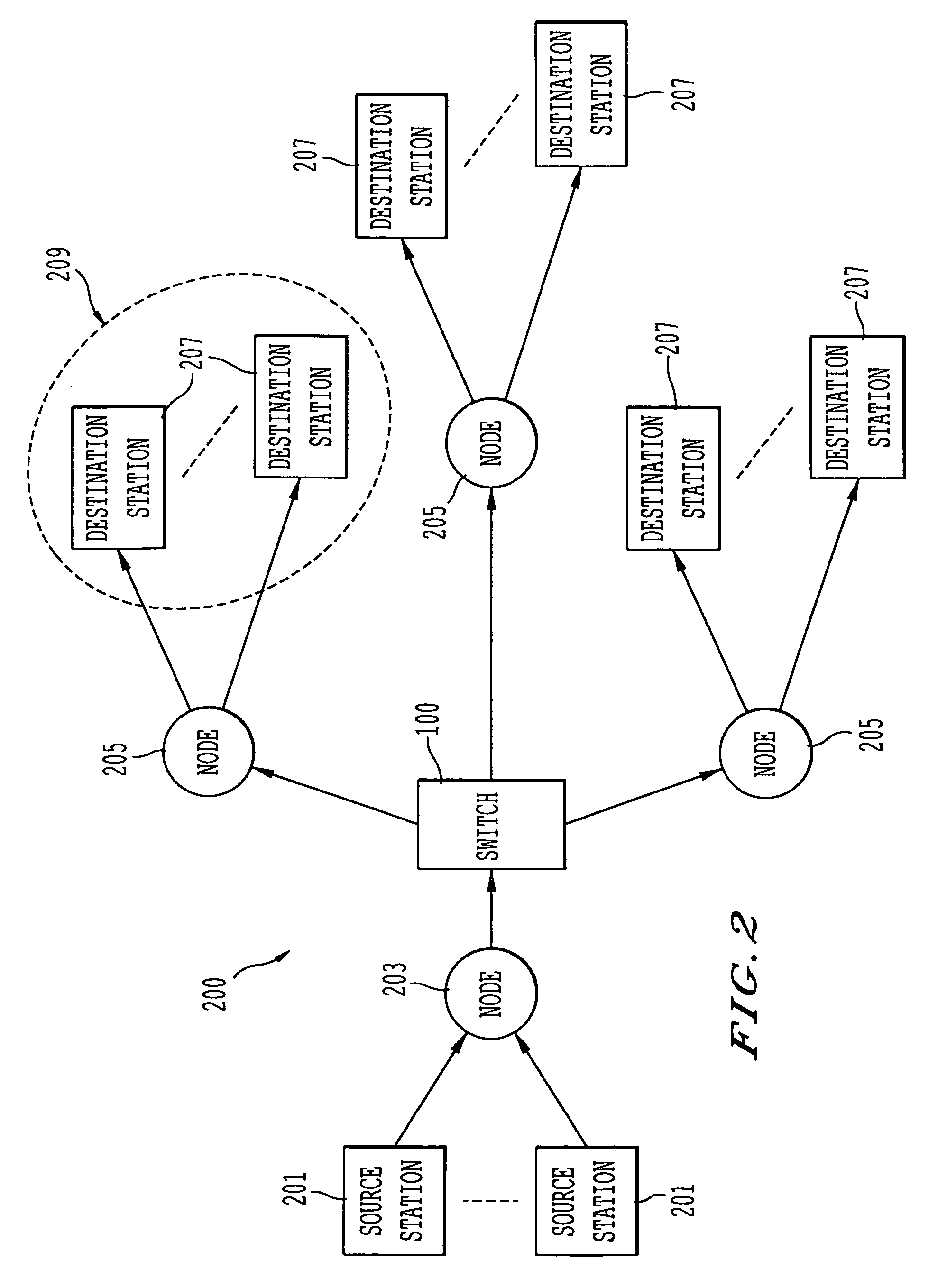
An approach for minimizing queuing delay of packets is disclosed. M number of queues are configured to store packets. A memory stores a search order table that has table entries corresponding to the M queues. Specifically, the table entries store values that correspond to relative positions of the M queues and that are selected based upon a transmission constraint of the communication system. A scheduler is coupled to the memory and is configured to schedule transmission of the packets stored in the M queues based upon the search order table. According to one embodiment of the present invention, this queuing mechanism is applied in a satellite communication system with transmission constraints to the downlink cells.

Description

CROSS-REFERENCES TO RELATED APPLICATION[0001]The present application is a continuation of U.S. application Ser. No. 09 / 670,124, filed Sep. 26, 2000 now abandoned, entitled “An Approach to Minimize Worst-Case Queueing Delay for a Switching Communication System with Transmission Constraints,” which claims the benefit of the earlier filing date of, U.S. Provisional Patent Application No. 60 / 198,580, filed Apr. 16, 2000, entitled “An Approach to Minimize Worst-Case Queueing Delay for a Switching Communication System with Transmission Constraints” the entireties of which are incorporated herein by reference.BACKGROUND OF THE INVENTION[0002]1. Field of the Invention[0003]The present invention relates generally to communication systems, and is more particularly related to providing fairness in the servicing of queues in a switching communication system.[0004]2. Discussion of the Background[0005]As businesses and society, in general, become increasingly reliant on communication networks to ...

Claims


Application Information

Patent Timeline
Patent Type & Authority Patents(United States)
IPC IPC(8): G06F15/16H04L12/56H04Q11/04
CPCH04Q11/0478H04L2012/5608H04L2012/5649H04L2012/5681
Inventor CHAN, WAI-CHUNGSU, CHI-JIUN
Owner U S BANK NAT ASSOC
Learn More