Thrust section wear preventor

Active Publication Date: 2008-05-13
BAKER HUGHES ESP INC
View PDF23 Cites 12 Cited by
  • Summary
  • Abstract
  • Description
  • Claims
  • Application Information

AI Technical Summary

Benefits of technology

[0010]In a preferred embodiment, the present invention provides a thrust section for use above a motor, which is positioned above a pump assembly. The thrust sectio

Problems solved by technology

However, in bottom intake applications the seal section is positioned below the motor and therefore is unable to prevent the motor shaft from moving upward during startup.
This problem is more pronounced in horizontal wells since the effect of gravity is virtually elimin

Method used


Image

  • Thrust section wear preventor
  • Thrust section wear preventor
  • Thrust section wear preventor

Examples


Example

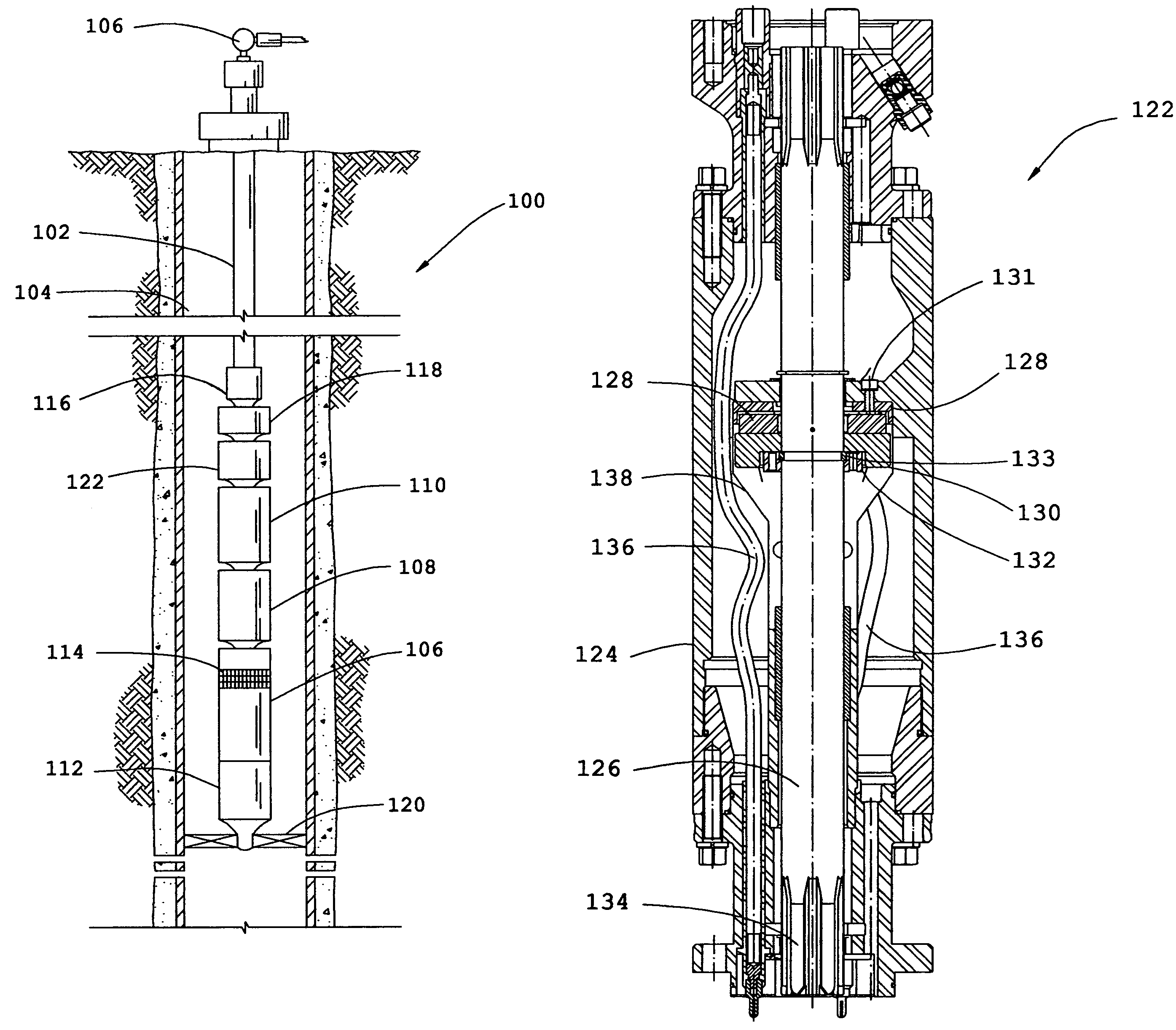
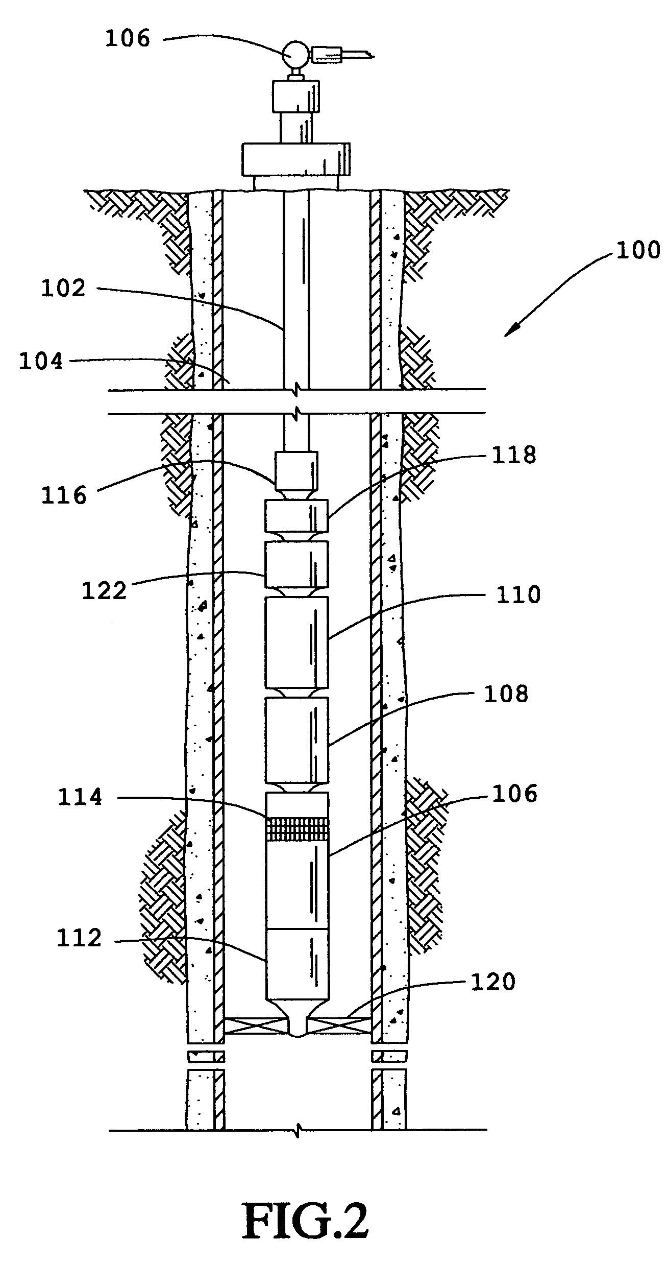
[0015]In accordance with a preferred embodiment of the present invention, FIG. 2 shows an elevational view of a pumping system 100 attached to coiled tubing 102. The pumping system 100 and coiled tubing 102 are disposed in a wellbore 104, which is drilled for the production of a fluid such as water or petroleum. As used herein, the term “petroleum” refers broadly to all mineral hydrocarbons, such as crude oil, gas and combinations of oil and gas. The coiled tubing 102 connects the pumping system 100 to the surface and supplies power to the pumping system 100 by use of a power cable (not shown) that extends through the coiled tubing 102. Although the pumping system 100 is primarily designed to pump petroleum products, it will be understood that the present invention can also be used to move other fluids. Also, it will be understood that the present invention can be used with production tubing instead of coiled tubing 102.

[0016]The pumping system 100 preferably includes some combinati...


PUM


Abstract

A thrust section for use above a motor preferably includes a housing, a thrust shaft, a thrust runner connected to the thrust shaft, a thrust bearing connected to the housing, and a motor lead guard. The motor is preferably positioned above a pump assembly. The thrust runner and thrust bearing prevent upward movement of the shaft.

Description

RELATED APPLICATIONS[0001]This application claims the benefit of U.S. Provisional Patent Application No. 60 / 532,872, entitled Prevention of Up-Thrust Wear on Center Tandem ESP Motors, filed Dec. 29, 2003, which is herein incorporated by reference.FIELD OF THE INVENTION[0002]This invention relates generally to the field of downhole pumping systems, and more particularly to an apparatus for protecting motors from wear caused by up thrust.BACKGROUND[0003]Submersible pumping systems are often deployed into wells to recover petroleum fluids from subterranean reservoirs. Typically, a submersible pumping system includes a number of components, including one or more electric motors coupled to one or more pump assemblies. The submersible pumping systems deliver the petroleum fluids from the subterranean reservoir to a storage facility on the surface. Each of the components in a submersible pumping system must be engineered to withstand the inhospitable downhole environment.[0004]Submersible ...

Claims


Application Information

Patent Timeline
IPC IPC(8): F04B17/00
CPCE21B43/128F04D13/10F04D29/0413
Inventor SAKAMOTO, STEPHEN M.NOAKES, AARON
Owner BAKER HUGHES ESP INC
Why Eureka
Try Eureka