
Automated transaction machine

Inactive Publication Date: 2008-05-13
DIEBOLD SELF SERVICE SYST DIV OF DIEBOLD NIXDORF INC
View PDF4 Cites 8 Cited by
  • Summary
  • Abstract
  • Description
  • Claims
  • Application Information

AI Technical Summary

Benefits of technology

[0009]It is a further object of exemplary embodiments to provide an automated banking machine that has improved capabilities for handling financial instrument sheets.
[0010]It is a further object of exemplary embodiments to provide an automated banking machine that facilitates proper alignment of ATM components during servicing activities.
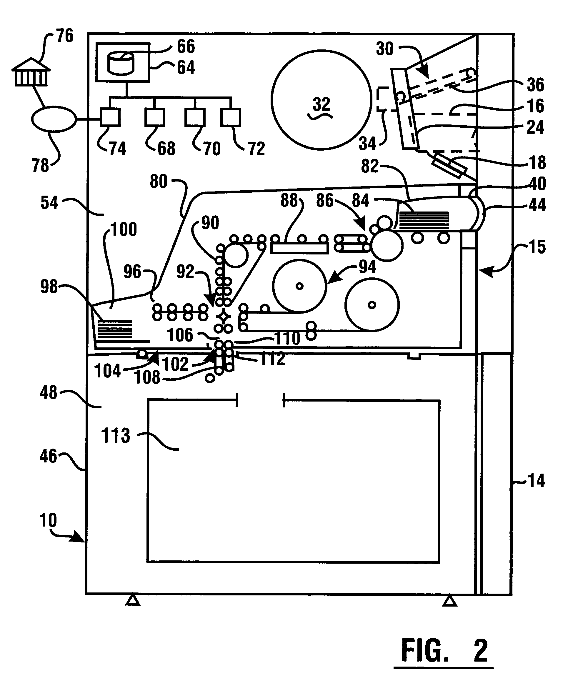
[0021]In an exemplary embodiment, the automated banking machine includes a removable sheet storage container selectively extending in the interior area, wherein when the sheet storage container is in an operative position, the sheet storage container is operative to receive sheets from the sheet acceptor and deliver the sheets to a storage area within the container. The exemplary embodiment includes a carriage assembly disposed within the interior area for supporting the sheet storage container in the interior area and moving the sheet storage container into and away from the operative position. The exemplary carriage assembly includes a stationary member extending in the interior area, a movable frame, and a frame directing mechanism. The frame directing mechanism directs the frame to move from an out / down position into an in / up position. In the in / up position, the sheet storage container is locked in an operative position by a catch and the frame moving mechanism is prevented from moving. A lever member is operative to unlock the catch holding the storage container in the operative position. In exemplary embodiments, the sheet storage container is locked in the operative position automatically, eliminating the need for a separate manual locking operation. Also in the exemplary embodiments, the frame is biased to automatically move toward the out / down position when the lever member unlocks the sheet storage container.

Problems solved by technology

However there are situations where machines must go out of service for preventative maintenance or remedial service.

Method used


Image

  • Automated transaction machine
  • Automated transaction machine
  • Automated transaction machine

Examples


Embodiment Construction

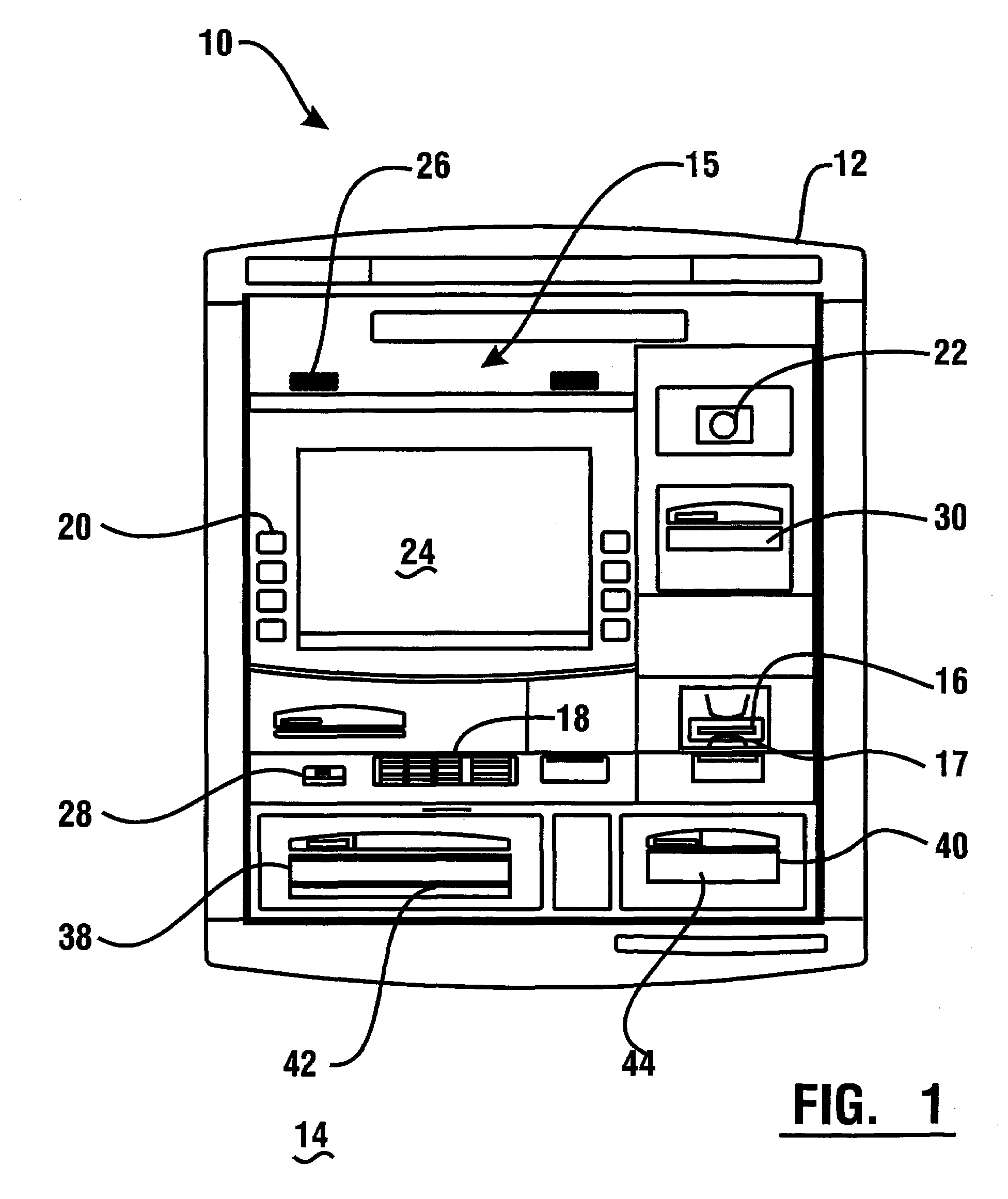
[0044]Referring now to the drawings and particularly to FIG. 1, there is shown therein a front plan view of an exemplary automated banking machine, which in this embodiment is an automated teller machine (“ATM”) 10. In this embodiment, ATM 10 is a through-the-wall type machine which includes a fascia 12. Fascia 12 is accessible to users of the machine who are positioned externally of the wall 14. In some embodiments wall 14 may be an exterior building wall and ATM 10 may be used in a walk-up or drive-up environment. Of course this configuration is merely exemplary and in other embodiments, other types of ATM configurations, such as standalone ATMs, may be used.

[0045]The exemplary ATM includes a user interface generally indicated 15. The user interface of the exemplary embodiment includes input devices for receiving inputs from users. These input devices include a card reader 16, a keypad 18, function keys 20 and an imaging device 22. In the exemplary embodiment the input devices may...


PUM


Abstract

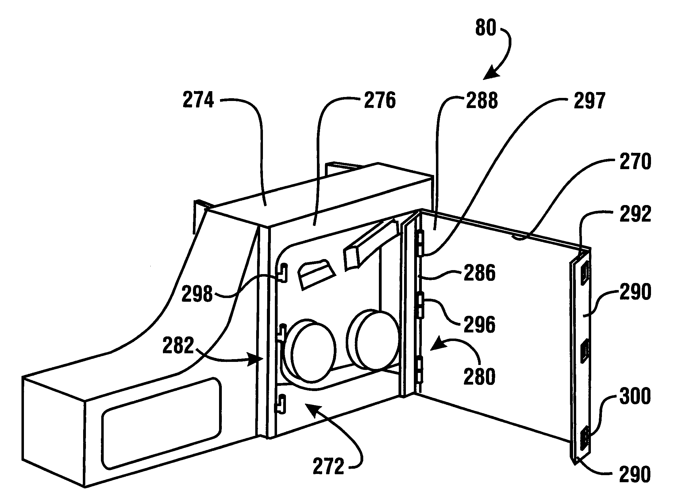
An ATM apparatus having a bulk sheet acceptor. The sheet acceptor is mounted in movable relation relative to a chest portion of the ATM. Access to an interior of the sheet acceptor for servicing may be made through an access opening. A service cover may be mounted at alternate mounting sites of the sheet acceptor housing in order to close the access opening. The interior of the sheet acceptor may be accessed by pivoting the cover on a set of tabs engaged in corresponding slots, or by selectively lifting the cover away from the tabs. The cover may be replaced by engagement of either a first set of tabs with corresponding first slots, or a second set of tabs with corresponding second slots.

Description

CROSS REFERENCE TO RELATED APPLICATIONS[0001]This application claims benefit pursuant to 35 U.S.C. § 119(e) of Provisional Application 60 / 724,671 filed Oct. 7, 2005, the disclosure of which is incorporated herein by reference.[0002]This application also claims benefit pursuant to 35 U.S.C. § 120 of U.S. application Ser. No. 10 / 688,621 filed Oct. 17, 2003, which claims benefit pursuant to 35 U.S.C. § 119(e) of provisional applications 60 / 419,681 filed Oct. 18, 2002 and 60 / 435,153 filed Dec. 19, 2002, the disclosures of each of which are incorporated herein by reference.TECHNICAL FIELD[0003]This invention relates to automated banking machines. Specifically embodiments relate to automated banking machines that have the capability of receiving financial instrument sheets such as notes, checks and other documents from users. Further embodiments relate to automated banking machines capable of receiving currency notes and recycling the currency back into circulation. Further embodiments re...

Claims


Application Information

Patent Timeline
IPC IPC(8): G06F19/00
CPCG07F19/20G07F19/202G07F19/205
Inventor GRAEF, H. THOMASDUNLAP, R. MATTHEWUTZ, ZACHARYSCHOEFFLER, DANIELGRIGGY, SHAWNRAMACHANDRAN, NATARAJAN
Owner DIEBOLD SELF SERVICE SYST DIV OF DIEBOLD NIXDORF INC
Learn More