Vibration isolating bushing with embedded angular position sensor

a technology of vibration isolation bushing and angular position sensor, which is applied in the field of contactless sensors, can solve the problems of sensor packaging, increasing costs, lowering efficiency, and increasing complexity and robustness, and achieves the effect of convenient packaging

Active Publication Date: 2008-05-13
NISSAN MOTOR CO LTD
View PDF53 Cites 10 Cited by
  • Summary
  • Abstract
  • Description
  • Claims
  • Application Information

AI Technical Summary

Benefits of technology

[0013]The present invention provides a robust, low cost angular position sensor configuration. The magnet, galvanomagnetic sensing element and a portion of the flux guide system are formed as a single rigid assembly. The only variable in the operation of the sensor is the effective air gap. The remainder of the flux guide system is mounted for limited rotation between limits of travel to ensure contactless operation. This arrangement has the advantage of requiring only one, relatively small permanent magnet and a single Hall effect sensor.
[0014]According to the preferred embodiment of the invention, a permanent magnet is employed in conjunction with a Hall effect sensor to form an elongated stator, which forms an opposed pole face at each end, which are mirror-image and radially tapered. Likewise, the rotor has a generally annular flux guide defining circumferentially opposed, radially tapered pole faces which are juxtapositioned with the stator poles to form respective air gaps there between. This arrangement has the advantage of a compact, robust design that can be easily tailored for a given application and expected range of relative rotation between the stator and rotor.
[0015]According to another aspect of the invention, means are provided to resiliently urge the sensor rotor and stator into a predetermined null position. This arrangement has the advantage of defining a range of operation without the necessity of employing hard stops, and preserve contactless operation.
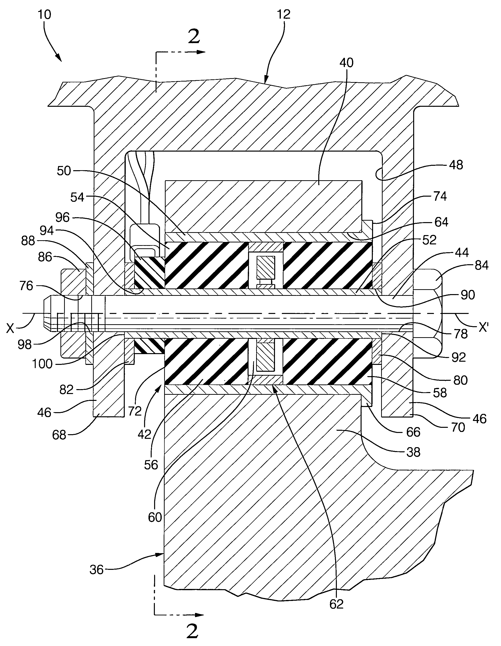
[0017]According to another aspect of the invention, the elastomeric member is bifurcated and the two halves axially separated to form a cavity there between. The sensor is centrally located between the elastomeric member halves. This arrangement has the advantage of hermetically sealing the sensor assembly, thus protecting it from harsh environmental effects found in many intended applications, such as automotive suspensions.
[0018]According to another aspect of the invention, the inner and outer members are formed of hardened steel and the elastomeric member is molded of solid rubber. This implementation allows the present invention to be conveniently packaged in a space traditionally reserved for a bushing alone. Restated, the present invention permits packaging of a rotary position sensor within an automotive suspension system without requiring any other offsetting design compromises.
[0020]According to still another aspect of the invention, means are provided to fix the relative rotational positions of the inner member and the stator as well as the relative rotational positions of the outer member and the rotor. This feature ensures proper orientation of the sensor components.

Problems solved by technology

Furthermore, the aforementioned process requires substantial attention to cause lowering of efficiency in adjusting alignment of the vehicle height sensor, further increasing costs.
These placement limitations are a result of not only the construction of the sensor itself, but also of the mechanical linkages used to connect the sensor to a component of the vehicle suspension system and a component of the vehicle body.
This increased functionality requires that more and more sensors be incorporated within the vehicle body and suspension system, making sensor packaging, as well as cost, complexity and robustness, more and more problematic.

Method used


Image

  • Vibration isolating bushing with embedded angular position sensor
  • Vibration isolating bushing with embedded angular position sensor
  • Vibration isolating bushing with embedded angular position sensor

Examples


Embodiment Construction

[0042]The present invention is intended for application in automotive vehicle suspension systems and will be described in that context. It is to be understood, however, that the present invention could also be successfully applied in many other applications. Accordingly, the claims herein should not be deemed as limited to the specifics of the preferred application as described hereunder.

[0043]The preferred embodiment of the present invention serves as both a bushing for mounting suspension system components to an automotive vehicle as well as a sensor to monitor the position of selected suspension components while the vehicle is in operation.

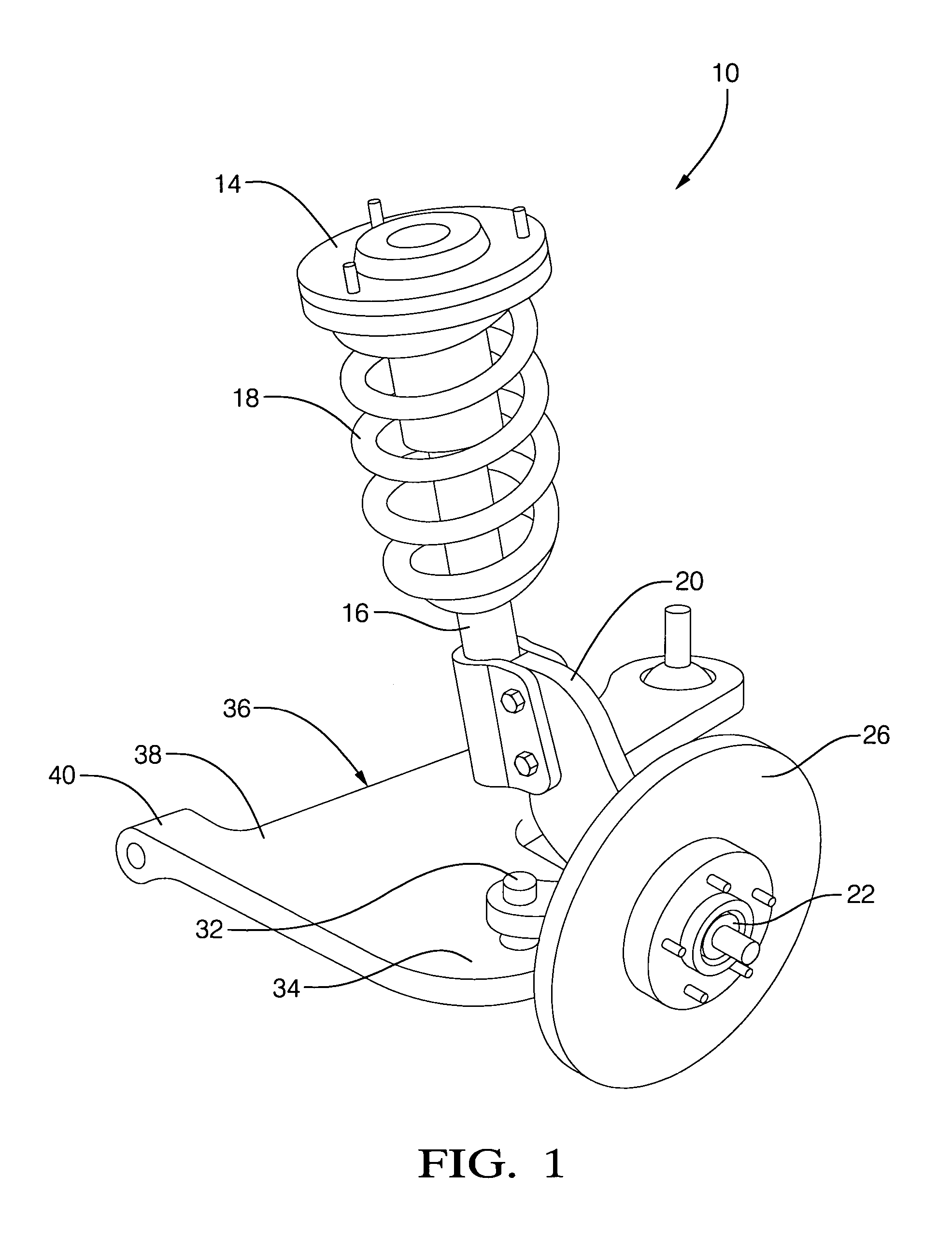
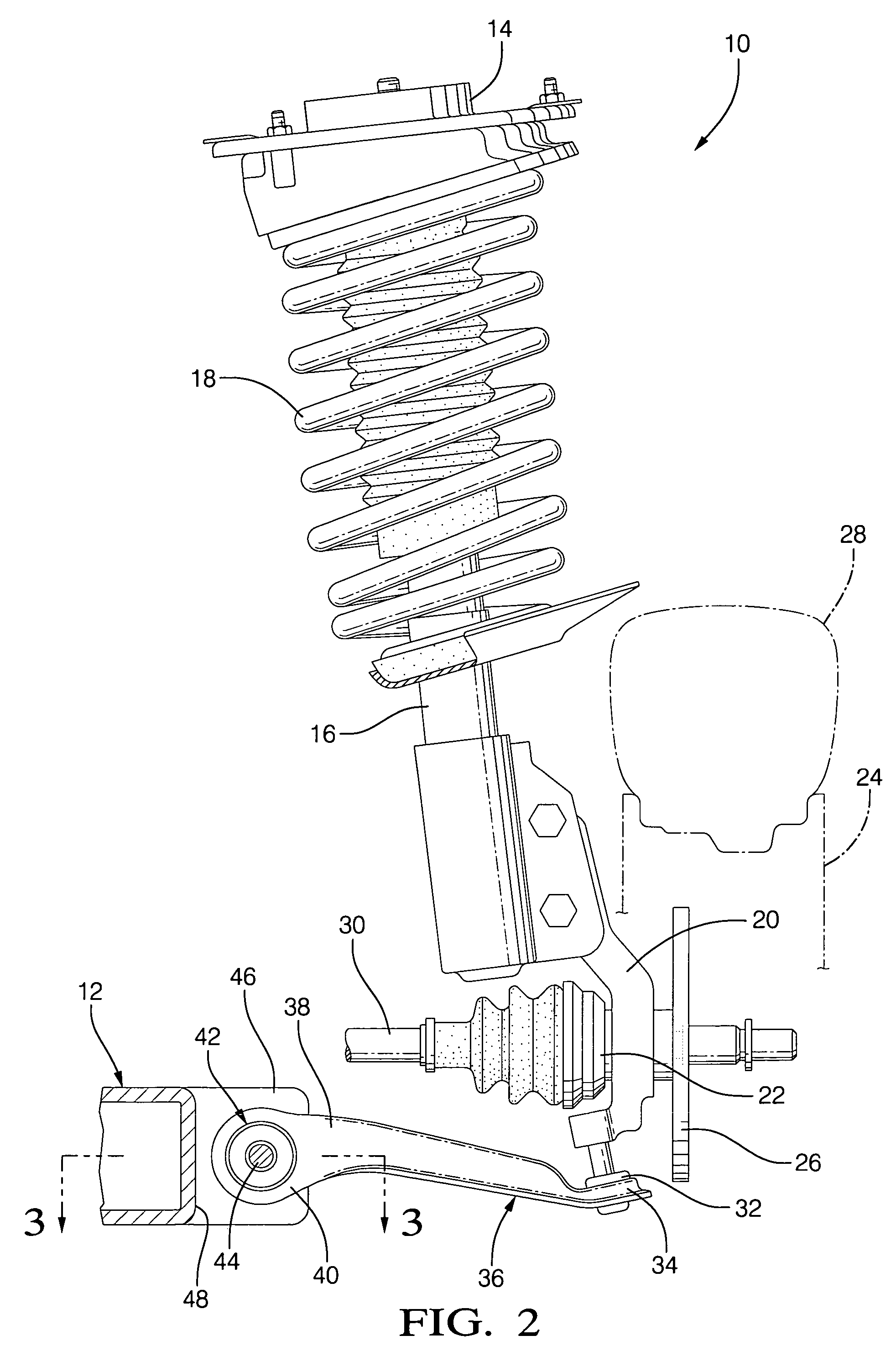
[0044]Referring to FIGS. 1 & 2, an automotive vehicle front wheel drive front suspension assembly 10 includes a shock tower (not illustrated) formed of sheet metal that is rigidly connected to the frame 12 of the host vehicle. Mounted to the shock tower is a strut tower cap 14 which, in turn, is mounted to a McPherson strut 16. The McPherson st...


PUM


Abstract

A bushing assembly adapted for application in vehicle suspension systems includes an outer, generally cylindrical bushing member, an inner generally cylindrical bushing member arranged concentrically within the outer member. The two bushing members are interconnected by an elastomeric member disposed there between and bonded thereto to permit limited rotational displacement between the external and internal bushing members. An angular position sensor is at least partially embedded within the elastomeric member and operative to produce an output signal indicative of the relative angular position of the external and internal bushing members. The sensor includes a stator assembly including a permanent magnet, a galvanomagnetic sensing element and a flux guide defining at least one pole face, and a rotor including a flux guide defining a second pole face. An air gap between the two pole faces varies dimensionally as a function of the relative angular position of the stator assembly and rotor.

Description

RELATED PATENT APPLICATION[0001]This application relates to corresponding U.S. Pat. Application No. 11 / 095,765, filed 31 Mar. 2005, entitled “Angular Position Sensor” identified as applicant docket no. DP-313694, and owned by a common assignee of interest.TECHNICAL FIELD[0002]The present invention relates generally to position sensors, and, more particularly, to contactless sensors for measuring the relative angular position between relatively rotatable objects, and, more particularly still, to the integration of such sensors within bushing systems such as those applied with automotive suspension systems.BACKGROUND OF THE INVENTION[0003]Angular and linear position systems are widely used in automatic control systems as feedback-sensing devices in one or more control loops of the system. In the automotive industry, a relatively recent trend is providing control-by-wire in lieu of the more traditional control provided by mechanical linkages, such as cables, rods and the like.[0004]Wit...

Claims


Application Information

Patent Timeline
Patent Type & Authority Patents(United States)
IPC IPC(8): F16F5/00
CPCB60G7/02B60G17/019G01D5/145F16F1/38B60G2204/11B60G2204/116B60G2204/143B60G2204/41B60G2400/05162B60G2400/252B60G2401/172F16F2230/08B60G2400/051G01D2205/40
Inventor URQUIDI, CARLOS A.RODRIGUEZ, HECTOR H.
Owner NISSAN MOTOR CO LTD
Why Eureka
Try Eureka