Bicycle drive unit of multi pedaling type

a multi-pedal, drive unit technology, applied in the direction of foot-driven levers, gearing, hoisting equipment, etc., can solve the problems of reduced exercise effect in terms of movement, increased feeling of fatigue, and lots of load on the leg, so as to reduce fatigue, less force, and increase the effect of movemen

Inactive Publication Date: 2008-05-13
HONG JAE HO
View PDF11 Cites 4 Cited by
  • Summary
  • Abstract
  • Description
  • Claims
  • Application Information

AI Technical Summary

Benefits of technology

[0004]Accordingly, the present invention has been made in view of the above problems, and it is an object of the present invention to provide a bicycle drive unit of multi-pedaling modes wherein a bicycle is moved forward based on several tens of pedaling modes whereby a driver's muscles are uniformly used, increasing the quantity of motion and reducing a feeling of fatigue, the bicycle is moved with less force on a slope, etc. and interest in riding the bicycle increases.
[0007]Furthermore, according to the present invention, a support bearing is inserted into the inner circumference of the ring gear, and the inner wheel of the support bearing is coupled to an outer circumference of an outer bearing housing, whereby the ring gear is prevented from fluctuating and deviating when being rotated and has a stabilized rotational force.

Problems solved by technology

Thus, a driver has to keep a certain posture for a long time while driving the bicycle.
This makes its exercise effect reduced in terms of the quantity of motion and a feeling of fatigue increased.
Accordingly, there are problems in that lots of load is applied to the leg and the driver loses interest in riding the bicycle.

Method used


Image

  • Bicycle drive unit of multi pedaling type
  • Bicycle drive unit of multi pedaling type
  • Bicycle drive unit of multi pedaling type

Examples


Embodiment Construction

[0018]The present invention will now be described in detail in connection with preferred embodiments with reference to the accompanying drawings.

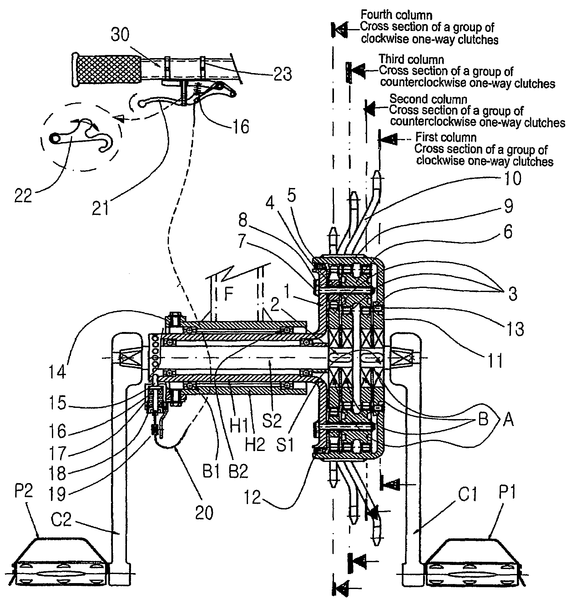
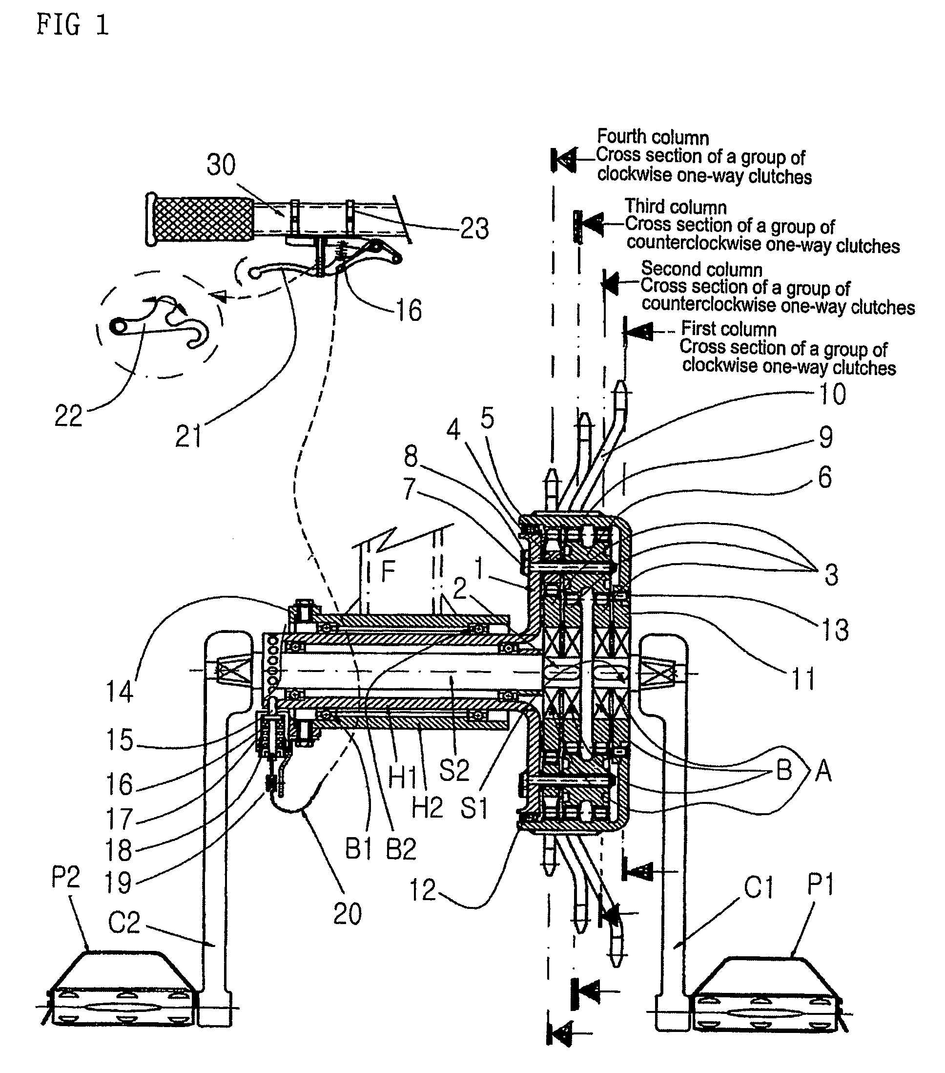
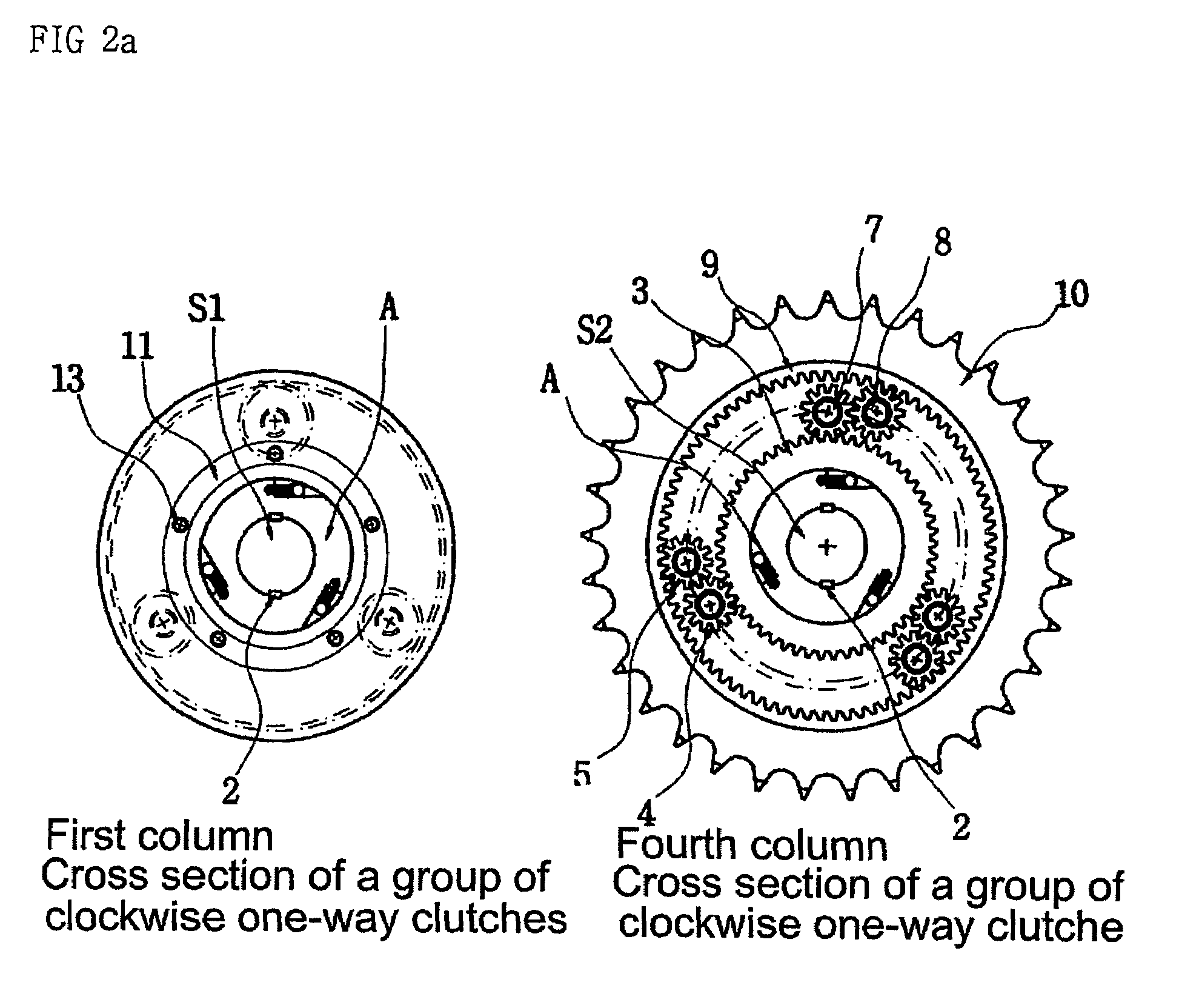
[0019]FIG. 1 is a cross-sectional view showing the bicycle drive unit according to an embodiment of the present invention. FIGS. 2a and 2b are detailed views of the bicycle drive unit shown in FIG. 1. FIGS. 3a to 3d show operational relationship in the bicycle drive unit according to the present invention.

[0020]In a common bicycle wherein pedals are stepped on to move the rear wheel of the bicycle in a clockwise direction, a bicycle drive unit according to the present invention includes a drive shaft S1 on one side and a drive shaft S2 on the other side which are each disposed on the right and left sides; and a pedal P1 on one side and a pedal P2 on the other side each of which has a saddle at one end of each of the drive shaft S1 and the drive shaft S2. In the above, the pedals P1 and P2 are attached to the ends of the pedal cranks C1 and ...


PUM


Abstract

The present invention relates to a bicycle drive unit of multiple pedaling modes, comprising a drive shaft on one side having a counterclockwise one-way clutch and a clockwise one-way clutch coupled thereto by means of sunk keys and the drive shaft is engaged with a ring gear having an outer circumference attached to a chain sprocket; a plurality of hollow turnabout gears engaged with the central gear of the drive shaft; a drive shaft on the other side having one side rotatably inserted into an inner bearing housing that is integrally formed with the rotary plate and the other side coupled to the inner wheels of the clockwise one-way clutch and the counterclockwise one-way clutch by means of the sunk keys and a plurality of turnabout gears, a two-way turnabout gear and a hollow turnabout gear.

Description

TECHNICAL FIELD [0001]The present invention relates to a bicycle drive type. More particularly, the present invention relates to a bicycle drive unit wherein right and left pedals are independently moved and a bicycle is always moved forward regardless of an angle even when the pedals are stepped on forward or backward using one foot or both feet, and the bicycle is moved backward, if necessary.BACKGROUND ART [0002]A bicycle is usually driven by means of clockwise pedaling. Thus, a driver has to keep a certain posture for a long time while driving the bicycle. Further, leg muscles are concentrated used in a single direction. This makes its exercise effect reduced in terms of the quantity of motion and a feeling of fatigue increased.[0003]Moreover, in case of a slope, although the weight of a driver is inclined behind, the pedaling must move in the clockwise direction. This makes the driver feel tired as higher as several times than a flat. Accordingly, there are problems in that lot...

Claims


Application Information

Patent Timeline
Patent Type & Authority Patents(United States)
IPC IPC(8): B62M1/02F16H3/44B62M1/36B62M3/00B62M9/04B62M9/10B62M11/14B62M11/18
CPCB62M1/24B62M1/36B62M3/00B62M11/14
Inventor HONG, JAE HO
Owner HONG JAE HO
Why Eureka
Try Eureka