Magnetic field sensor for measuring the rotational speed of a turboshaft

a technology of magnetic field and turbocharger, which is applied in the direction of instruments, galvano-magnetic hall-effect devices, machines/engines, etc., can solve the problems of increasing the rotational speed, increasing the weight of the engine, and increasing the cost of the engine, so as to achieve the effect of simple production

Inactive Publication Date: 2008-05-13
SIEMENS VDO AUTOMOTIVE CORP +1
View PDF9 Cites 14 Cited by
  • Summary
  • Abstract
  • Description
  • Claims
  • Application Information

AI Technical Summary

Benefits of technology

[0007]An object of the present invention is therefore to provide a sensor for measuring the rotational speed of a turbocharger which can be produced simply and at low cost and also can be integrated in a turbocharger without major structural modifications.
[0009]This positioning of the sensor element allows commercially available electronic sensor elements such as Hall sensors or magnetoresistive (MR) sensors to be used because temperatures that are tolerable for the sensor element prevail outside the turbocharger. The pole piece used concentrates the magnetic field with respect to the sensor element, so that a sufficiently high field strength that can be measured well penetrates the sensor element even when there is a relatively great distance between the magnet rotating on the turboshaft and the sensor element. The pole piece can be integrated in the compressor housing, with only minor disturbance of the air stream in the air inlet of the compressor for example. The signal generated by the sensor element according to the present invention allows the boost-pressure control valve to be controlled very quickly and precisely, or the turbine geometry of VTG superchargers can be changed very quickly and precisely, to avoid exceeding the permissible rotational speed of the running gear. As a consequence, the turbocharger can always be operated very close to its speed limit, whereby it achieves its maximum efficiency. Furthermore, the relatively great safety margin from the maximum speed limit which is required by conventional pressure-controlled turbochargers is not required.
[0010]According to one embodiment, the sensor element is a Hall sensor element. Hall sensor elements are very well suited for sensing the variation of a magnetic field and can therefore be used very well for the speed sensing. Hall sensor elements can be commercially obtained at very low cost and can also be used at temperatures up to approximately 160° C.
[0011]As an alternative to this, the sensor element may be formed as a magnetoresistive (MR) sensor element. MR sensor elements are for their part well suited for sensing the variation of a magnetic field and can be commercially obtained at low cost.
[0014]The pole piece may be molded on the sensor housing. In the injection-molding process, the pole piece can be connected to the sensor housing very simply and at low cost.
[0015]According to a specific embodiment, the pole piece is formed as a pin. The long and narrow pin form makes it possible for the magnetic field to be concentrated and guided over a long distance, the air flow in the compressor only being influenced to very small degree. The pole piece exhibits very advantageous behavior in the air stream if it is formed in an aerodynamic manner.

Problems solved by technology

However, an increase in the swept volume leads in principle to engines that are heavier, have larger dimensions, and are consequently more expensive.
Increasing the rotational speed entails considerable problems, in particular in the case of larger engines, and is limited for technical reasons.
Inadmissible exceeding of the rotational speed of the running gear would cause it to be destroyed, which would be equivalent to total loss of the turbocharger.
However, these types of turbochargers are particularly susceptible to damage caused by exceeding the permissible maximum speed.
Depending on the design of the turbocharger, even exceeding the speed limit by approximately 5% leads to complete destruction of the turbocharger.
However, this control is relatively sluggish, since the pressure buildup when the rotational speed of the running gear is exceeded takes place with a time delay.
Therefore, the speed control for the turbocharger with the boost pressure monitoring must intervene in the highly dynamic range (power-off) by appropriately early reduction of the boost pressure, which leads to a loss of efficiency.
Direct measurement of the rotational speed at the compressor wheel or at the turbine wheel proves to be difficult, since for example the turbine wheel is exposed to extreme thermal loading (up to 1000° C.
This method is complex and expensive, since at least one eddy current sensor would have to be integrated in the housing of the compressor in the direct vicinity of the compressor blades, which is likely to be extremely difficult because of the high precision with which components of a turbocharger are produced.
Apart from the precise integration of the eddy current sensor in the compressor housing, sealing problems arise, problems which, on account of the high thermal loading of a turbocharger, can only be overcome by sophisticated modifications of the structural design of the turbocharger.

Method used


Image

  • Magnetic field sensor for measuring the rotational speed of a turboshaft
  • Magnetic field sensor for measuring the rotational speed of a turboshaft
  • Magnetic field sensor for measuring the rotational speed of a turboshaft

Examples


Embodiment Construction

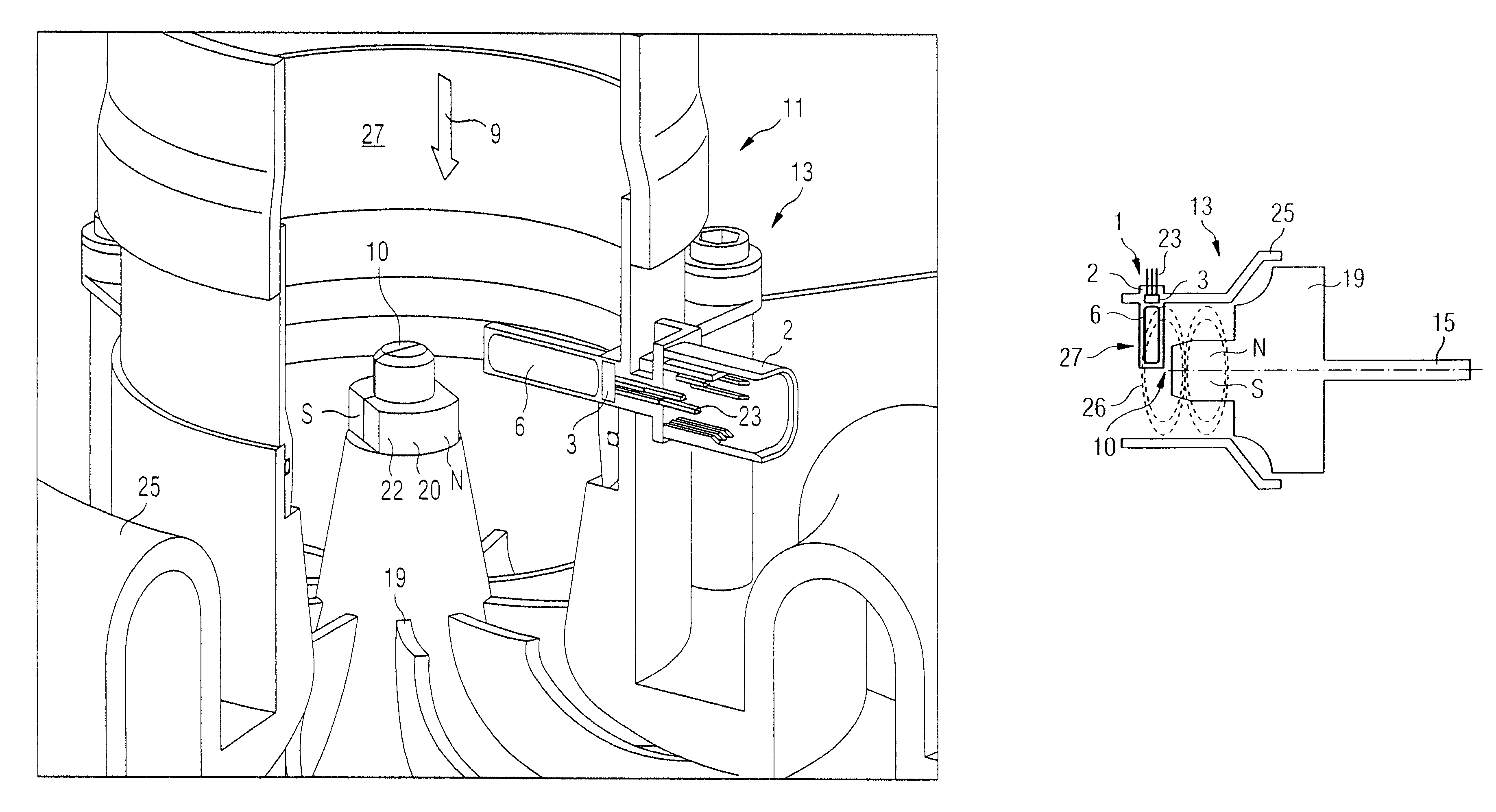
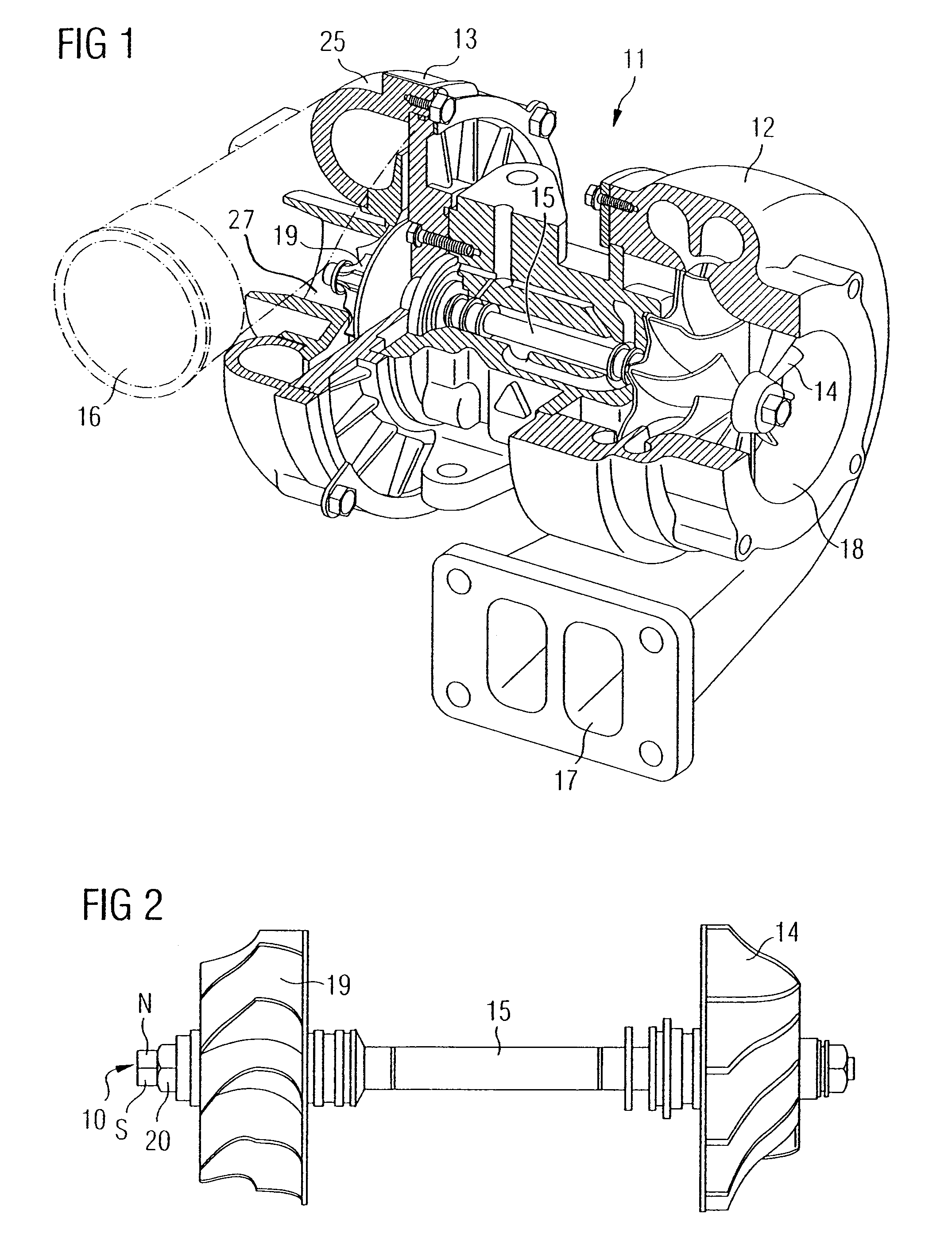
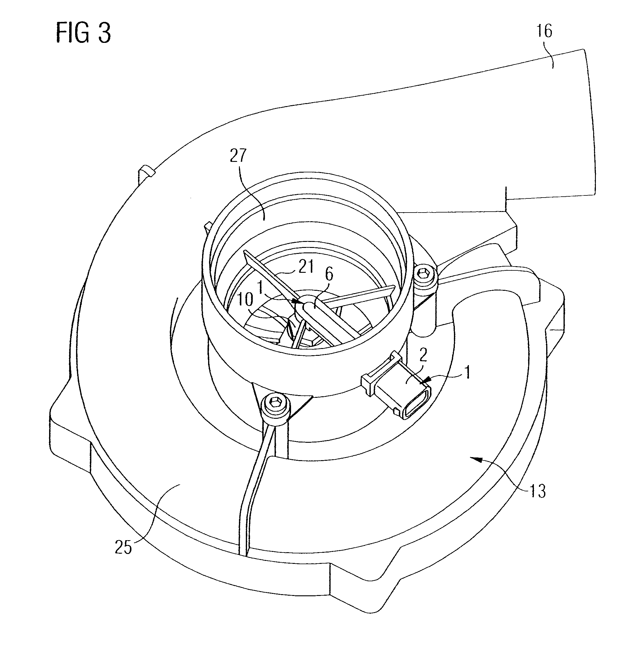
[0038]FIG. 1 shows a conventional exhaust gas turbocharger 11 with a turbine 12 and a compressor 13. A compressor wheel 19 is rotatably mounted in the compressor 13 and is connected to one end of a turboshaft 15. Another end of the rotatably mounted turboshaft 15 is connected to a turbine wheel 14. Hot exhaust gas from an internal combustion engine (not represented here) is admitted into the turbine 12 via a turbine inlet 17 which sets the turbine wheel 14 in rotation. The exhaust gas stream leaves the turbine 12 through a turbine outlet 18. The turbine wheel 14 is connected to the compressor wheel 19 by the turboshaft 15. Consequently, the turbine 12 drives the compressor 13. Air is sucked into the compressor 3 through an air inlet 27, and is then compressed in the compressor 13 and supplied to the internal combustion engine via the air outlet 16.

[0039]FIG. 2 shows the turboshaft 15 and the compressor wheel 19. The compressor wheel 19 is produced for example from an aluminum alloy ...


PUM


Abstract

A sensor for measuring the rotational speed of a turboshaft of a turbocharger includes a sensor housing and a sensor element which is positioned in the sensor housing and which senses a variation of a magnetic field caused by the rotation of the turboshaft. In order to provide a sensor for measuring the rotational speed of a turboshaft which can be produced simply and at low cost and also can be integrated in a turbocharger without major structural modifications, the sensor element can be positioned outside the turbocharger, on or in a compressor housing, and a pole piece is arranged on the sensor element in such a way that it concentrates the magnetic field in the sensor element.

Description

BACKGROUND OF THE INVENTION[0001]The present invention relates to a sensor for measuring the rotational speed of a turboshaft of a turbocharger with a sensor housing and a sensor element positioned in the sensor housing and which senses a variation of a magnetic field caused by the rotation of the turboshaft.[0002]The power generated by an internal combustion engine depends on the air mass and the corresponding amount of fuel that can be made available to the engine for combustion. If an increase in the power of the internal combustion engine is desired, an increased amount of combustion air and fuel must be supplied to the engine. In a naturally aspirated engine, this increase in power is achieved by an increase in the swept volume or by increasing the rotational speed. However, an increase in the swept volume leads in principle to engines that are heavier, have larger dimensions, and are consequently more expensive. Increasing the rotational speed entails considerable problems, in...

Claims


Application Information

Patent Timeline
Patent Type & Authority Patents(United States)
IPC IPC(8): G01B7/30
CPCF01D21/003F02B37/12F02B39/16G01P3/44G01P3/487G01P3/488Y02T10/144F05D2220/40Y02T10/12
Inventor BIBER, PETERGILCH, MARKUSROUX, JEAN-LOUISSIMONNET, ANTOINE
Owner SIEMENS VDO AUTOMOTIVE CORP
Why Eureka
Try Eureka