
Voltage controlled oscillator comprising an injection pulling compensation circuit

a voltage control and compensation circuit technology, applied in the field of rf circuits, can solve the problems of complex implementation, deterioration of vco performance, leakage of harmonic signals, etc., and achieve the effect of simple and inexpensive implementation and good results

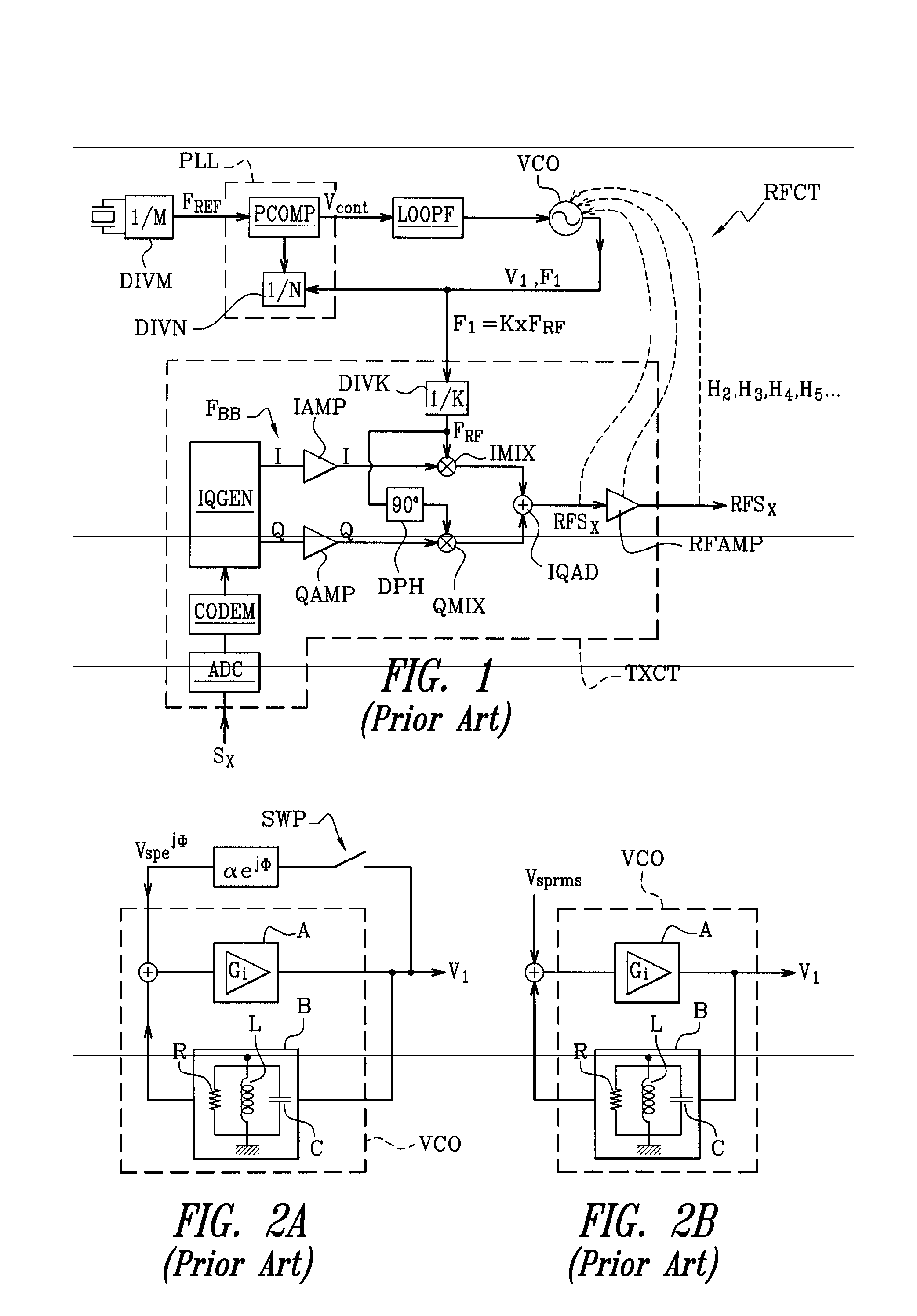
Inactive Publication Date: 2008-05-13
ST ERICSSON SA
View PDF5 Cites 24 Cited by
  • Summary
  • Abstract
  • Description
  • Claims
  • Application Information

AI Technical Summary

Benefits of technology

This approach effectively reduces or eliminates injection pulling in VCOs, stabilizing their operation without the need for complex setups or multiple VCOs, improving RF circuit performance by addressing the root cause of spurious signals.

Problems solved by technology

In radio frequency circuits using VCOs, the performances of the VCOs are deteriorated by leaks of harmonic signals, due to “injection pulling” also known as “injection locking”.
It is well known that the involuntary injection of this harmonic component into the core of the VCO, by various spurious paths, deteriorates the performances of the VCO.
This solution is however complex to implement and increases the cost price of the RF circuits, which is passed on at the end of the chain to the selling price of the mobile telephones.
However, the disadvantage of the heterodyne systems is that they require the use of at least two VCOs, as well as additional mixers and filters, and are therefore costly and bulky.

Method used


Image

  • Voltage controlled oscillator comprising an injection pulling compensation circuit
  • Voltage controlled oscillator comprising an injection pulling compensation circuit
  • Voltage controlled oscillator comprising an injection pulling compensation circuit

Examples


Embodiment Construction

Experimental and Theoretical Bases of the Present Invention

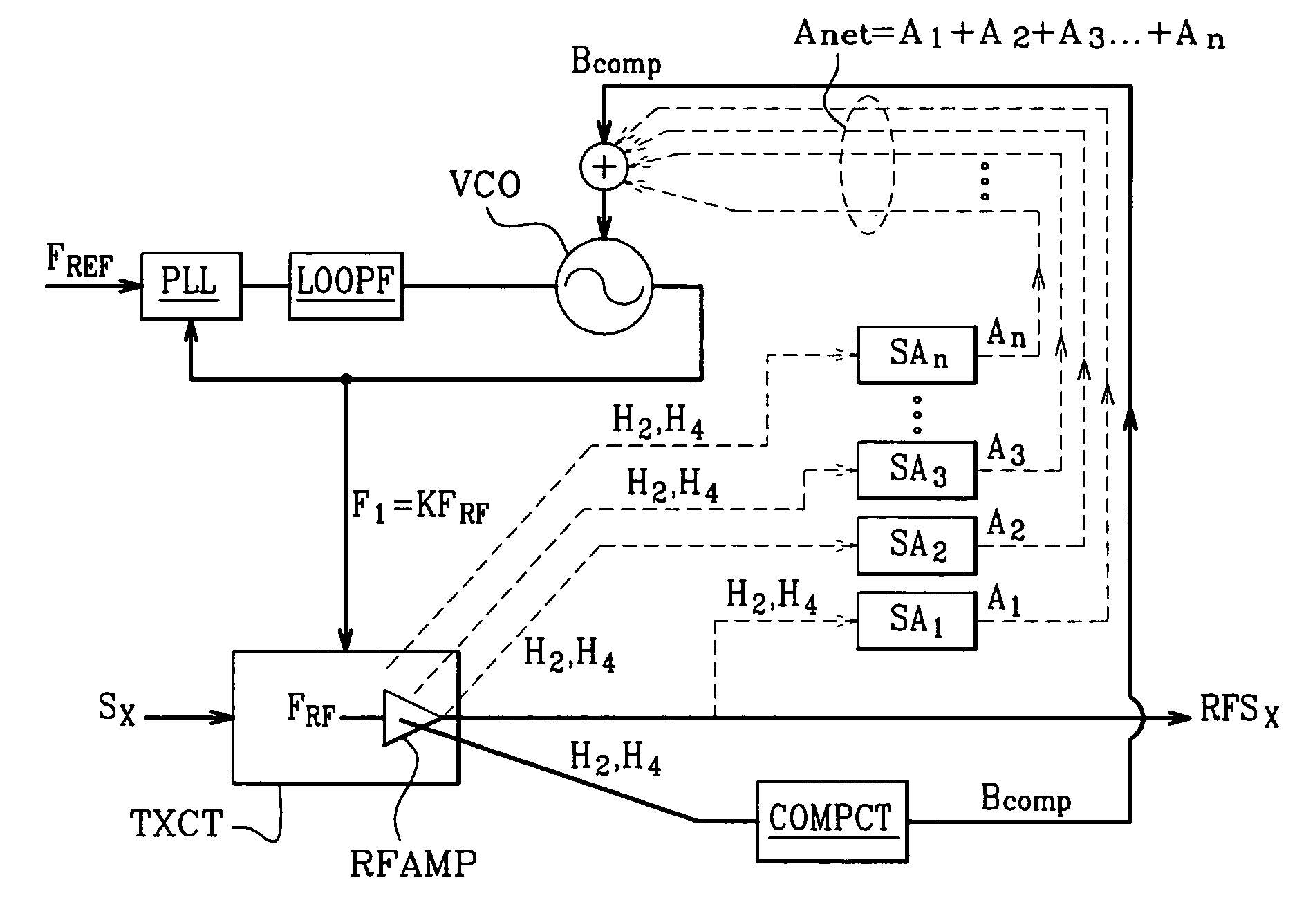
[0090]As explained above, the principle of the present invention is to inject a compensation signal into a VCO that neutralises in phase and in amplitude a resulting spurious signal equal to the vector sum of the incident spurious signals coming from a harmonic component delivered by a modulation circuit.

[0091]Before describing examples of embodiments of compensation circuits enabling this compensation signal to be generated, various experimental observations, theoretical studies and hypotheses having led to the present invention will be succinctly described.

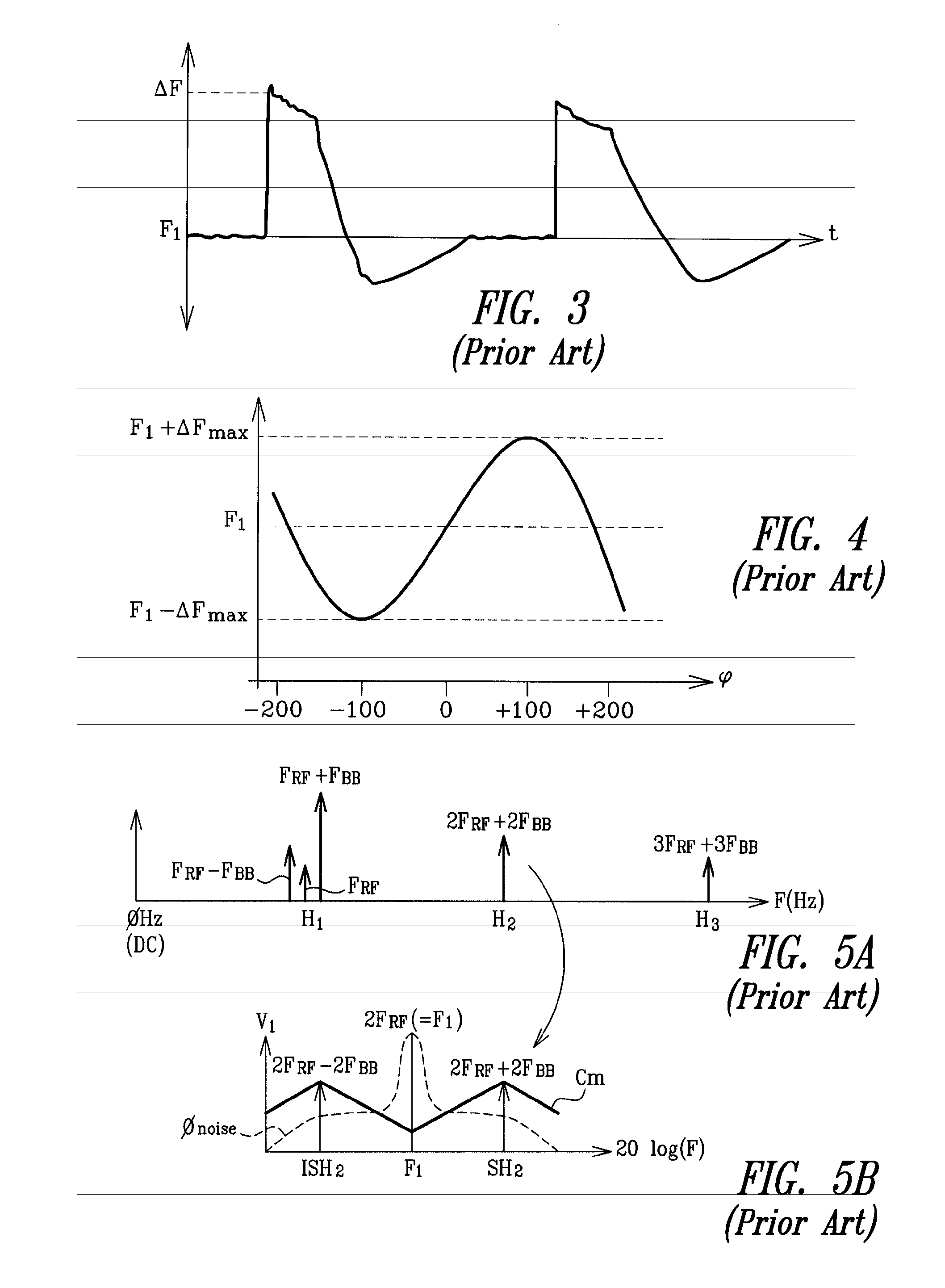
[0092]The deterioration caused by the injection pulling results in two distinct phenomena. Firstly, there is instantaneous frequency jumps in the VCO, and secondly a spurious modulation leading to a substantial phase error and spurious lines in the spectrum of frequencies of the VCO. It must be shown that these two phenomena have a single cause taking the form of a singl...


PUM


Abstract

The present invention relates to a method for stabilising the operation of a voltage controlled oscillator driven by a phase locked loop, the voltage controlled oscillator delivering an RF signal and receiving through at least one spurious path a harmonic component of a frequency equal or proximate to that of the RF signal, capable of disturbing its operation by injection pulling. According to the present invention, the method comprises a step of injecting into the voltage controlled oscillator an injection pulling compensation signal, the phase and the amplitude of which are adjusted so as to neutralise the effects of the spurious harmonic component. Application particularly to phase modulation IQ circuits in radiotelephony.

Description

BACKGROUND OF THE INVENTION[0001]1. Field of the Invention[0002]The present invention relates to voltage controlled oscillators or VCOs.[0003]The present invention relates more particularly to an RF circuit comprising a voltage controlled oscillator delivering an RF signal, a phase locked loop to control the voltage controlled oscillator, a modulation circuit receiving the RF signal and delivering a modulated signal comprising at least one RF harmonic component capable of disturbing the voltage controlled oscillator by injection pulling.[0004]2. Description of the Related Art[0005]In radio frequency circuits using VCOs, the performances of the VCOs are deteriorated by leaks of harmonic signals, due to “injection pulling” also known as “injection locking”.[0006]The present invention aims to remove, or at least to reduce, the injection pulling in the VCOs.[0007]For a better understanding, FIG. 1 shows a classical application of a VCO in the area of radiotelephony. In this Figure a cir...

Claims


Application Information

Patent Timeline
Patent Type & Authority Patents(United States)
IPC IPC(8): H03L7/00H03B1/04H03B5/12H03L7/06H03L7/099H03L7/18
CPCH03L7/06H03B5/1231H03B5/1215H03B5/1243H03B2202/046H03B2202/088H03L7/099H03L7/18
Inventor NAYLER, PETER
Owner ST ERICSSON SA
Learn More