
Control system methods and apparatus for inductive communication across an isolation barrier

a control system and inductive communication technology, applied in the field of control systems, can solve the problems of increasing combustion activity and diving the temperature upwards, limited data transfer bandwidth, and knocking out field devices

Active Publication Date: 2008-05-13
SCHNEIDER ELECTRIC SYST USA INC
View PDF10 Cites 34 Cited by
  • Summary
  • Abstract
  • Description
  • Claims
  • Application Information

AI Technical Summary

Benefits of technology

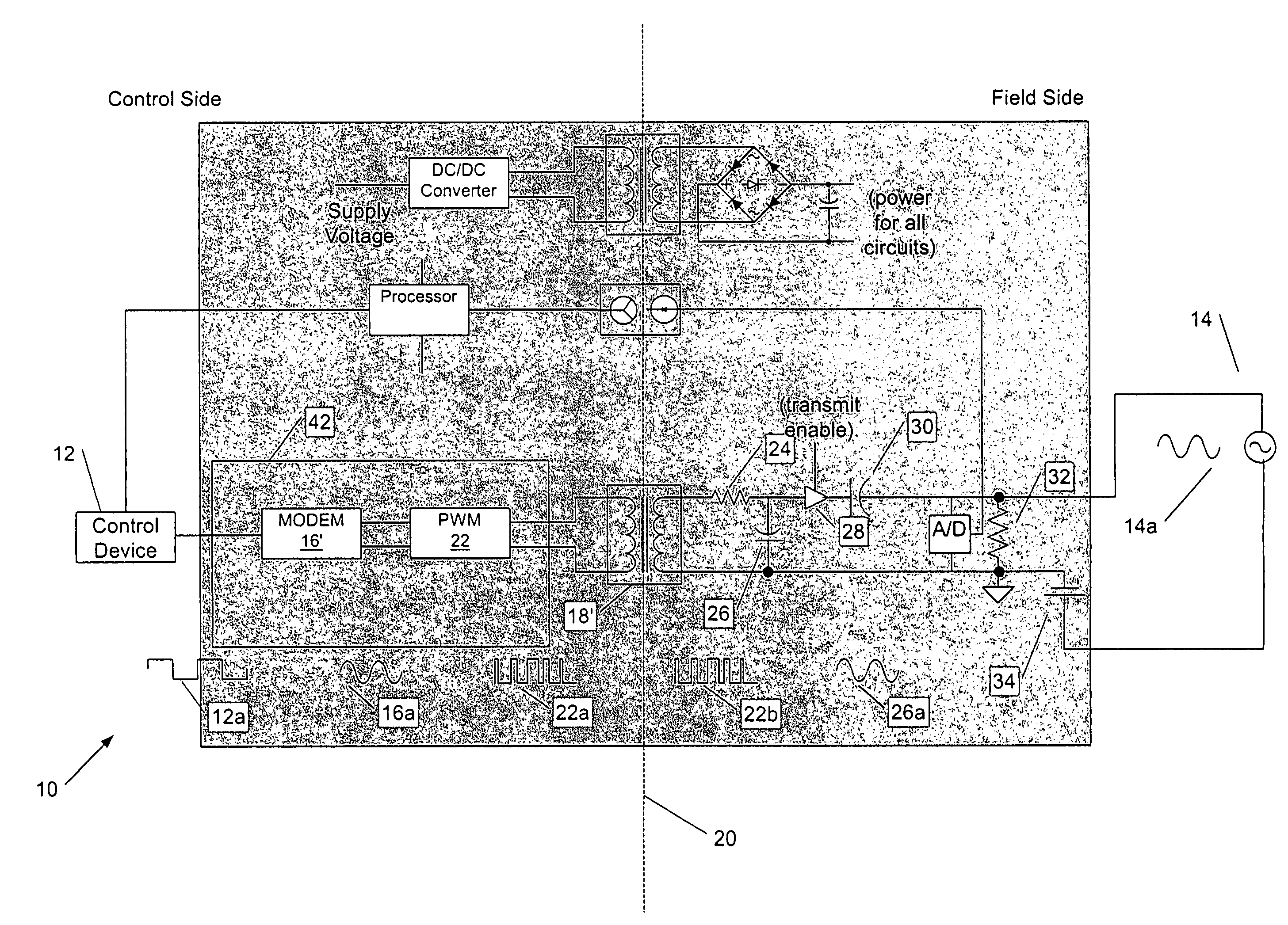
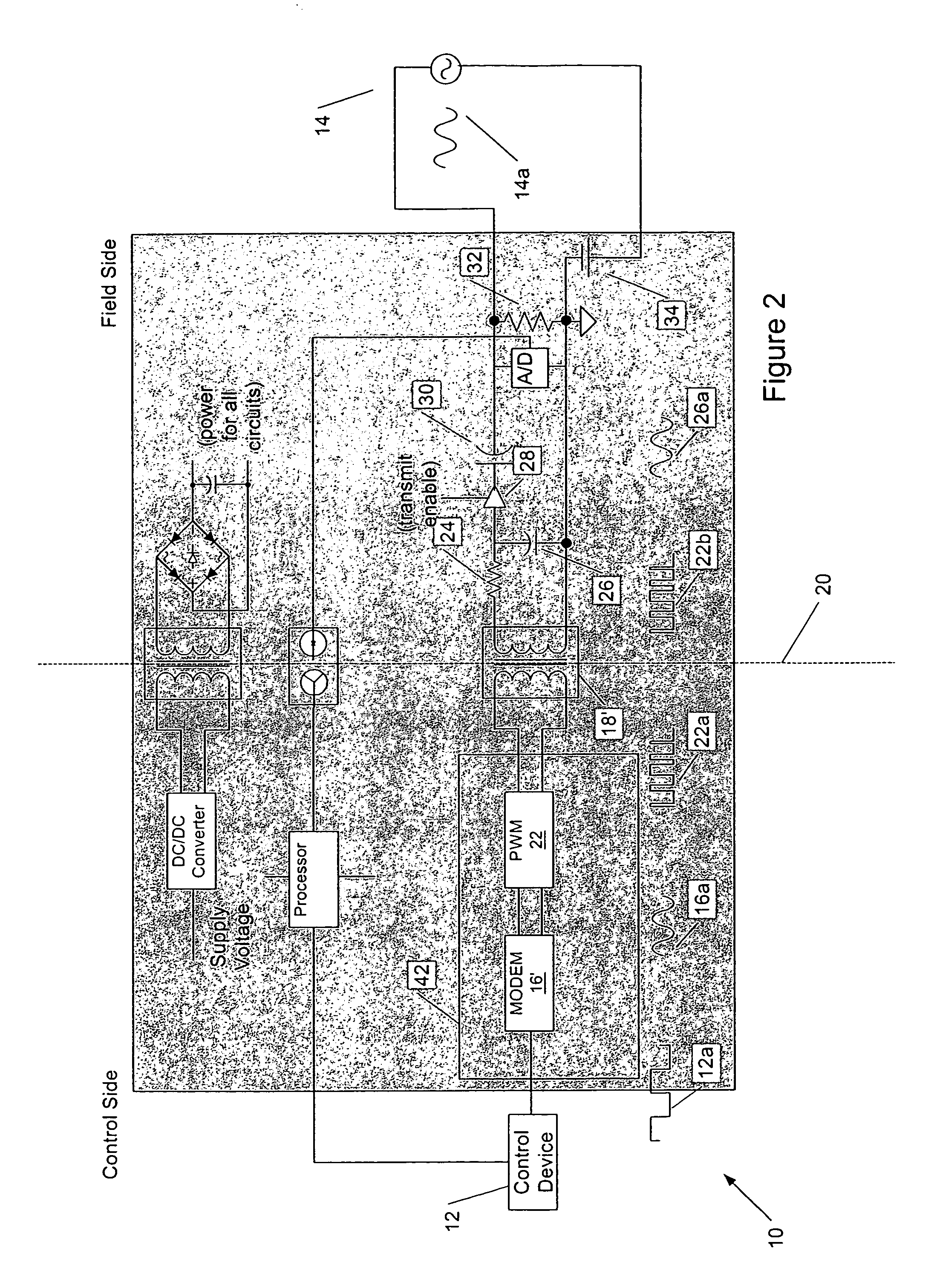
The invention provides improved apparatus for transferring information between control devices over a galvanic or other isolation barrier. The apparatus includes a modulator that generates a pulse width modulated (PWM) signal from a frequency shift keying (FSK) or other frequency modulated (FM) signal containing the information being transferred. The PWM signal is then transferred across the isolation barrier using a transformer or other circuit element. The PWM signal is demodulated to analog form for application to a second control device, e.g., a field device or controller. The invention also provides apparatus for transferring information from the second control device to the first control device using an amplitude modulated (AM) signal generated from an FSK signal embodying the information. The invention allows for the transmission of information encoded in analog FSK signals over small, low power transformers between electrically isolated components of a control system.

Problems solved by technology

If the chamber temperature is too low, the control algorithm may call for incrementally opening the dampers, thereby, increasing combustion activity and diving the temperature upwards.
The reverse is likewise true: static discharges or standard line voltages present in the plant control room could knock out field devices, or worse, if circuited back to the power-generating equipment.
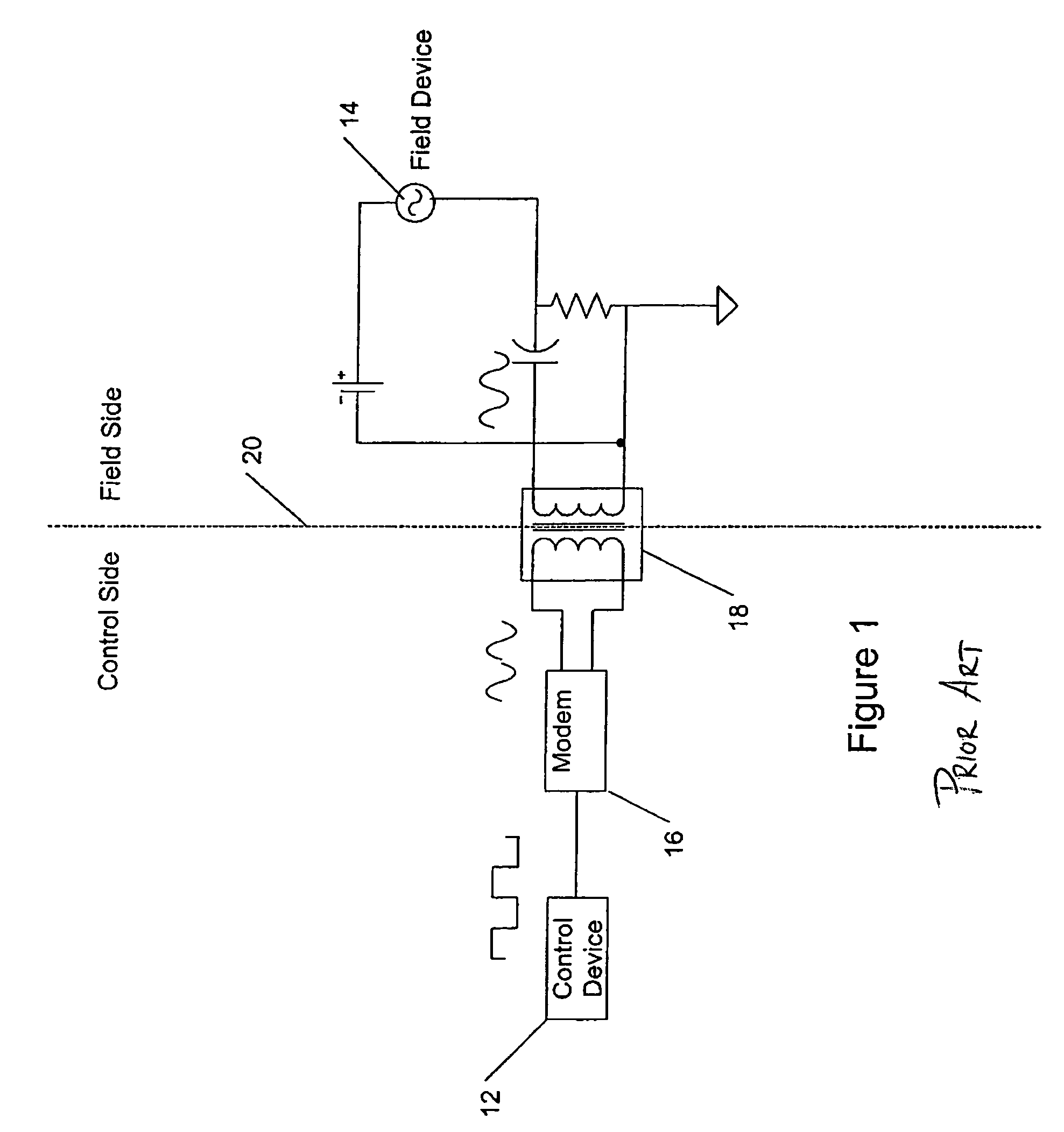
However, when utilizing conventional circuits such as shown in FIG. 1, the bandwidth of the data transfers is limited—unless resort is had to unduly large transformers.
This can be problematic in applications where power or physical space are limited.

Method used


Image

  • Control system methods and apparatus for inductive communication across an isolation barrier
  • Control system methods and apparatus for inductive communication across an isolation barrier
  • Control system methods and apparatus for inductive communication across an isolation barrier

Examples


Embodiment Construction

[0053]FIG. 1 illustrates a prior art system for galvanic isolation of the components of a process control system. Here, a control device 12 (e.g., a controller) generates a digital signal for controlling a field device 14. Those signals are transmitted to a modem (which may be integral to the control device or, more typically, coupled to it via a serial port) and modulated to analog form, more specifically, an frequency shift keying form, which can be a “tone” signal in the range of 1-5 kHz. A transformer 18 is used to pass the FSK signal across an isolation barrier 20 from the “control side” of the system to the “field side,” where it can be applied to the field device directly, via a modem, or otherwise. By a similar mechanism, data (or other control) signals generated by the field device 14 are passed back over the transformer in FSK form, demodulated to digital form and routed to the control device 12 for processing. A drawback of systems of the type illustrated in FIG. 1 is the...


PUM


Abstract

Improved control apparatus and methods transfer information between devices, such as controllers and field devices, utilizing a modulator that generates a pulse width modulated (PWM) signal containing information to be transferred by a first of the devices, e.g., the controller, to the second device. A transformer or other inductive device transfers the PWM signal across the isolation barrier, where it is demodulated to analog form for application to the second device, e.g., the field device. Information transferred from the second device to the first device can be transferred in an amplitude modulated (AM) signal that utilizes, as its carrier, a fixed duty cycle output of the modulator that generates the PWM signal.

Description

[0001]This application claims the benefit of priority of U.S. Provisional Patent Application Ser. No. 60 / 249,145, filed Nov. 16, 2000, entitled CONTROL SYSTEM METHODS AND APPARATUS FOR INDUCTIVE COMMUNICATION ACROSS AN ISOLATION BARRIER.BACKGROUND OF THE INVENTION[0002]The invention relates to control systems and, more particularly, to methods and apparatus for transferring information across an isolation barrier between control devices such as, by way of non-limiting example, field devices and the systems that monitor and / or control them. The invention has application in the exchange of data / control signals in process, industrial, environmental and other control systems.[0003]The terms “control” and “control systems” refer to the control of a device or system by monitoring one or more of its characteristics. This is used to insure that output, processing, quality and / or efficiency remain within desired parameters over the course of time. In many control systems, digital data proces...

Claims


Application Information

Patent Timeline
Patent Type & Authority Patents(United States)
IPC IPC(8): H04L27/10H03K7/08H03K11/00H04B5/00
CPCG01D21/00H03K7/08H03K11/00H04L27/10H04L25/0266H04L25/4902H04B5/005H04B5/75
Inventor CALVIN, JAMES G.
Owner SCHNEIDER ELECTRIC SYST USA INC
Learn More