Electric power generation control system

a control system and power generation technology, applied in the direction of electric control, machines/engines, mechanical equipment, etc., can solve the problems of reduced output voltage limited current of electric power generation of vehicle alternators, low response speed, etc., to reduce the circuit configuration of electric power generation control systems, reduce processing burden or load of external control devices, and increase the reliability of the whole system

Active Publication Date: 2008-05-20
DENSO CORP
View PDF16 Cites 3 Cited by
  • Summary
  • Abstract
  • Description
  • Claims
  • Application Information

AI Technical Summary

Benefits of technology

[0008]It is an object of the present invention to provide an electric power generation control system capable of stabilizing the rotation speed of a vehicle engine during its idle state, capable of preventing a voltage drop of the output voltage of electric power generation of a vehicle alternator when electric loads are turned on, namely, activated, and capable of increasing a response speed of the output voltage of the electric power generation.

Problems solved by technology

However, the technique disclosed in the former related art JP-H5-227675 involves a drawback of greatly decreasing the output voltage of the electric power generation of the vehicle alternator when the electric loads are turned on in the idle state of the vehicle engine because the current of the electric power generation of the vehicle alternator is limited when all cylinders of the vehicle engine fall in deactivated operation state under the idle state of the vehicle engine.
Further, the technique disclosed in the latter related art JP-H8-140284 involves a drawback of having a low response speed because it takes a relatively long time until the output voltage of the electric power generation reaches a specified voltage level according to increasing an actual exciting current although the increasing speed of the exciting current becomes large when detecting the turned-on or the activation of the electric loads,

Method used


Image

  • Electric power generation control system
  • Electric power generation control system
  • Electric power generation control system

Examples


first embodiment

[0034]A description will be given of a vehicular electric power generation system composed mainly of a vehicular electric power generator and an electric power generation control system according to the first embodiment of the present invention with reference to the attached drawings.

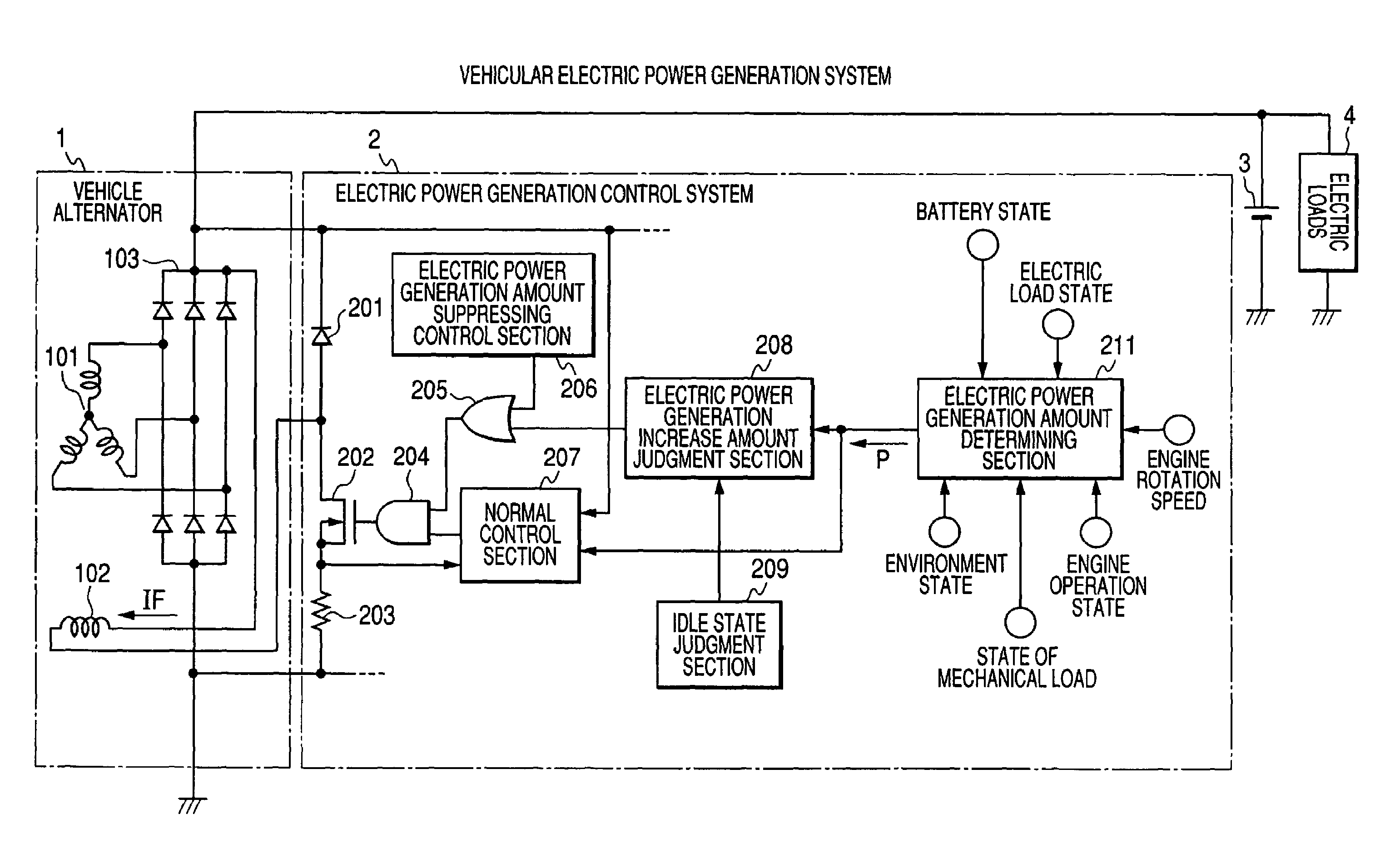
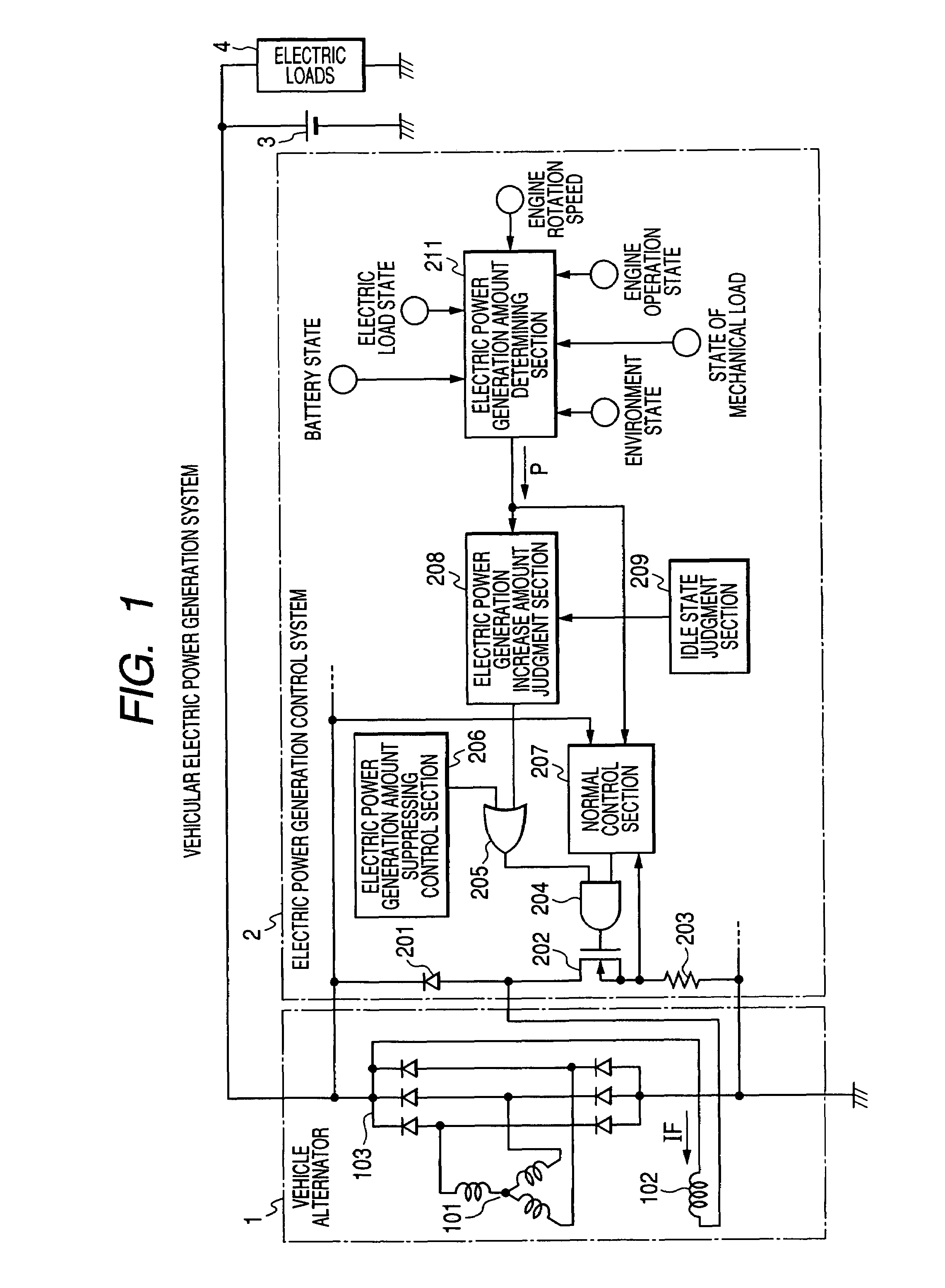
[0035]FIG. 1 is a view showing an entire configuration of the vehicular electric power generation system composed of the vehicle alternator 1 (as a vehicular electric power generator) and the electric power generation control system 2 according to the first embodiment of the present invention.

[0036]The vehicle alternator 1 is driven by a vehicle engine (an internal combustion engine) mounted on a vehicle and supplies the electric power to a battery 3 and various types of electric loads 4. The electric power generation control system 2 controls the electric power generation of the vehicle alternator 1.

[0037]The vehicle alternator 1 is equipped mainly with a stator having a three phase stator winding 101,...

second embodiment

[0077]Next, a description will now be given of the electric power generation control system composed mainly of an electric power generation control device 2A and an engine ECU 2B according to the second embodiment of the present invention.

[0078]FIG. 6 is a view showing an electric power generation system composed of the electric power generation control system equipped mainly with the electric power generation control device 2A and the engine ECU 2B according to the second embodiment of the present invention.

[0079]The example shown in FIG. 6 takes the dispersion configuration. That is, the electric power generation control device 2A is equipped mainly with the reflux diode 201, the switching element 202, the sense resistance 203, the AND circuit 204, the OR circuit 205, the electric power generation amount suppressing control section 206, the normal control section 207, and a communication terminal 301.

[0080]The engine ECU 2B is equipped with the judgment section 208 for judging an ...

third embodiment

[0093]Next, a description will now be given of the electric power generation control system composed mainly of an electric power generation control device and an engine ECU according to the third embodiment of the present invention.

[0094]FIG. 8 is a view showing an electric power generation system composed of the electric power generation control system equipped mainly with the electric power generation control device 2A-1 and the engine ECU 2B-1 according to the third embodiment of the present invention.

[0095]In the configuration of the third embodiment shown in FIG. 8, the electric power generation control device 2A-1 has the reflux diode 201, the switching element 202, the sensing resistance 203, the AND circuit 204, the OR circuit 205, the electric power generation amount suppressing control section 206, the normal control section 207, the judgment section 208 for judging the increasing amount of the electric power generation, and the communication terminal 301. The engine ECU 2...


PUM


Abstract

An electric power generation control system has an electric power generation amount determining section for determining an electric power generation request amount of a vehicle alternator by monitoring vehicle conditions, an electric power generation amount increase judgment section for judging presence / absence of an electric power generation amount increase request to the vehicle alternator based on change of the electric power generation request amount in passage of time, an idle state judgment section for judging whether or not a vehicle engine falls in idle operation state, and an electric power generation amount suppressing control section for suppressing an electric power generation amount of the vehicle alternator. In the idle operation state of the vehicle engine and the presence of the electric power generation amount increase request, the electric power generation amount suppressing control section halts the control of suppressing the electric power generation of the vehicle alternator.

Description

CROSS-REFERENCE TO RELATED APPLICATION[0001]This application is related to and claims priority from Japanese Patent Application No. 2006-102725 filed on Apr. 4, 2006, the contents of which are hereby incorporated by reference.BACKGROUND OF THE INVENTION[0002]1. Field of the Invention[0003]The present invention relates to an electric power generation control system capable of controlling the electric power generation state of a vehicular A.C. generator (a vehicle alternator), which is driven by a vehicle engine (an internal combustion engine), for supplying electric power to a battery and electric loads mounted on a vehicle.[0004]2. Description of the Related Art[0005]An electric power generation control apparatus has been well known, which is capable of suppressing the amount of current of the electric power generation of a vehicle alternator when all cylinders of a vehicle engine (or an internal combustion engine) fall in deactivated operation state during its idle state. Japanese ...

Claims


Application Information

Patent Timeline
Patent Type & Authority Patents(United States)
IPC IPC(8): F02D41/16
CPCH02J7/1438H02J7/1446H02P9/30F02D41/083
Inventor ASADA, TADATOSHIMAEHARA, FUYUKI
Owner DENSO CORP
Why Eureka
Try Eureka