Bilevel, cantilevered, angled platform welding cart with cylinder rack

Inactive Publication Date: 2008-05-20
HOLLIS FRED BORRAS
View PDF7 Cites 15 Cited by
  • Summary
  • Abstract
  • Description
  • Claims
  • Application Information

AI Technical Summary

Benefits of technology

[0007]The general purpose of the present invention, which will be described subsequently in greater detail, is to provide a heavy-duty welding cart designed for use in industrial setting that is able to safely transport 600 pounds of welding related equipment, while providing a margin of safety against tipping henceforth unseen in the industry.
[0009]In accordance with the invention, an object of the present invention is to provide an improved welding cart capable of smoothly transporting up to 600 pounds of welding related equipment across the terrain of an industrial facility.
[0010]It is another object of this invention to provide an improved welding cart that allows easy access to all items on and around the cart as well as the gas, water and electrical connections.
[0011]It is a further object of this invention to provide a welding cart that offers increased visibility of the controls on the welding unit in industrial lighting situations, and to allow ample room for the connection of service lines to the rear of the welding units.

Problems solved by technology

First, they are generally of a mechanical fastener assembled, light gauge steel fabrication and as such have load limits that are marginal for their intended use.
Second, the support pillars on two-tiered welding units tend to obstruct and hamper the attachment of the gas, water and electrical line connections to the rear of the welding units.
Third, these modified carts, do not roll well in the terrain encountered in the industrial welding environment and is such are prone to tipping and sudden stops.
Lastly, the addition of gas cylinders to the welding cart alters the cart's center of balance and makes the cart dangerous to move.
Often these light-duty carts buckle or distort under the weight of heavier welding units.
Similarly, the wheels commonly break or fail to roll smoothly under such heavy weights.
Although these welding carts are intended to transport welding units and the along smooth floors, smooth floors are commonly, not the case.
The wheels of such units are generally susceptible to damage from the floor they roll on.
The combination of heavy loads and an uneven rolling surface leads to the premature failure of the cart wheels and the creation of potentially dangerous situations.
A secondary problem is caused by the direct overhead lighting of most industrial and commercial welding facilities.
This makes selection of the welding parameters difficult to accomplish.
This is a constant problem since often small incremental changes in these settings are necessary to facilitate proper welds.

Method used


Image

  • Bilevel, cantilevered, angled platform welding cart with cylinder rack
  • Bilevel, cantilevered, angled platform welding cart with cylinder rack
  • Bilevel, cantilevered, angled platform welding cart with cylinder rack

Examples


Embodiment Construction

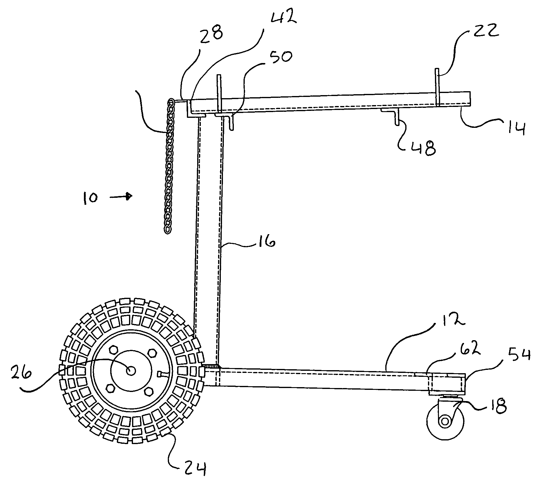
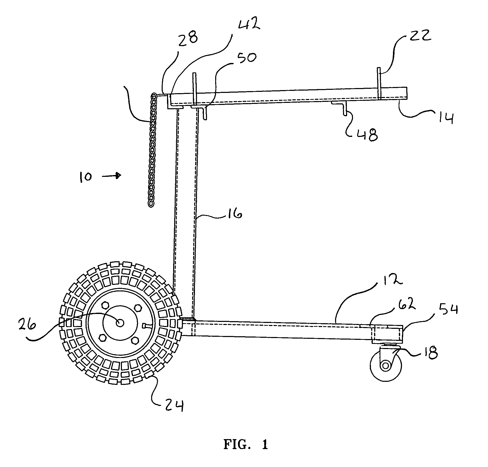
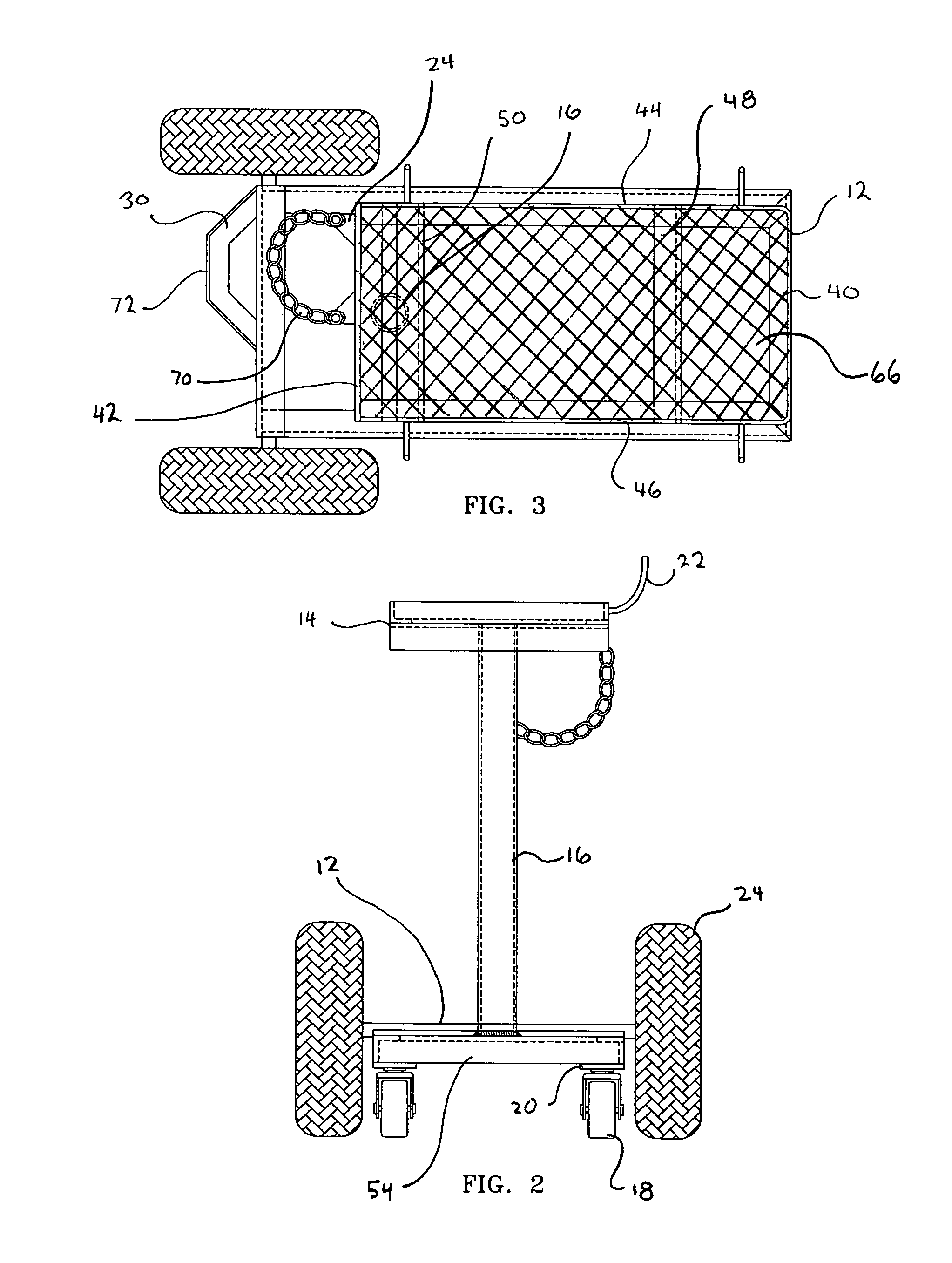
[0025]The present invention relates to a bi level welding cart, designed to safely transport gas cylinders, having a one piece welded steel frame utilizing a single pillar design and an upward angled second platform. The structural configuration is such that the weight of any gas cylinders and that of any equipment on the top platform are centered directly over the rear axle to minimize tipping. A gas cylinder is secured by a chain long enough to substantially encircle the cylinder and mechanically connected at two points to a cylinder securing plate. The rear wheels are of a large pneumatic style while the front wheels are of a larger swivel castor design. The cart frame is of a one piece steel welded design of a minium 3 / 16 inch thick steel that can be factory assembled or site assembled. The main support pillar can be offset and / or can be of a telescoping and pivoting design.

[0026]Referring now to FIG. 1, a side view of the preferred embodiment cart 10, the general arrangement of...


PUM


Abstract

The present invention is a bilevel, cantilevered, welding cart with a rear cylinder rack and angled top platform. The cart frame is of a one piece heavy gauge steel that is capable of transporting in excess of 600 pounds. The front caster wheels and rear axle are welded to the frame leaving only the rear wheels to be attached. It has a single rear pillar support that can be offset in front of the gas cylinder support to allow easy connection of the gas, water air and or power lines to the welding unit. The gas cylinder support positions the weight of the gas cylinder adjacent the rear axle to prevent tipping.

Description

BACKGROUND OF THE INVENTION[0001]The present invention relates to a extremely heavy-duty welding cart and more particularly to an improved welding cart designed for use in industrial environments.[0002]Although rolling welding carts are commonplace in industrial and commercial welding environments, generally, these are multipurpose carts that have been adapted to carry heavy welding units and the associated equipment. These adapted carts have several drawbacks. First, they are generally of a mechanical fastener assembled, light gauge steel fabrication and as such have load limits that are marginal for their intended use. Second, the support pillars on two-tiered welding units tend to obstruct and hamper the attachment of the gas, water and electrical line connections to the rear of the welding units. Third, these modified carts, do not roll well in the terrain encountered in the industrial welding environment and is such are prone to tipping and sudden stops. Lastly, the addition of...

Claims


Application Information

Patent Timeline
IPC IPC(8): B62B3/00B62B1/00B62B5/00
CPCB23K9/323B62B3/10B62B2202/022B62B2206/06
Inventor HOLLIS, FRED BORRAS
Owner HOLLIS FRED BORRAS
Why Eureka
Try Eureka