Two way non leaking flow valve with full-open capability

a flow valve, full-open technology, applied in the direction of valve operating means/release devices, manufacturing tools, transportation and packaging, etc., to achieve the effect of small leakage and full blow-off capability

Inactive Publication Date: 2008-05-20
PARKER INTANGIBLES LLC
View PDF19 Cites 13 Cited by
  • Summary
  • Abstract
  • Description
  • Claims
  • Application Information

AI Technical Summary

Benefits of technology

[0010]In pick-and-place applications, a suction head is connected to the chamber shuttle cavity wall and negative pressure is applied to the fluid flow opening. To pick up a work piece, the suction head is applied to the surface with sufficient force to overcome the biasing force thereby allowing fluid flow between the fluid flow opening and the aperture in the second cavity wall portion. Fluid flow through the shuttle cavity will eliminate the pressure differential between the fluid flow opening and the shuttle cavity and enable the development of negative pressure in the cavity existing between the suction head and the work piece surface. The force applied by the negative pressure operating against the work piece surface is greater than the biasing force and maintains the valve-open state. If however the work piece is removed, or if the work piece surface is sufficiently porous, the force applied by the negative pressure is insufficient to overcome the biasing force, which will therefore force the shuttle cavity into the valve-closed state.
[0011]A first objective of the invention is to provide a two way valve with very small leakage and full blow-off capability.

Problems solved by technology

If however the work piece is removed, or if the work piece surface is sufficiently porous, the force applied by the negative pressure is insufficient to overcome the biasing force, which will therefore force the shuttle cavity into the valve-closed state.

Method used


Image

  • Two way non leaking flow valve with full-open capability
  • Two way non leaking flow valve with full-open capability
  • Two way non leaking flow valve with full-open capability

Examples


first embodiment

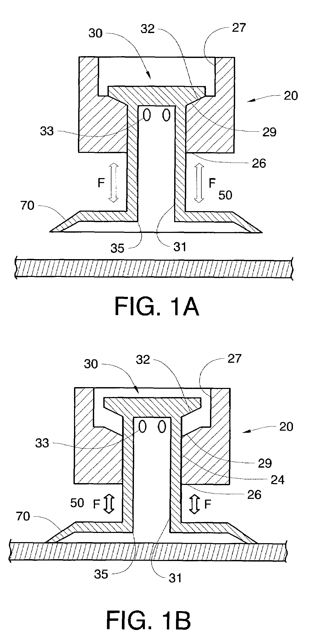
[0019]the invention is depicted in FIGS. 1a &1b. The first valve embodiment comprises a housing 20 that has a valve chamber bounded by a valve chamber wall 24 and having a first valve chamber opening bounded by a first valve chamber opening edge 26 and a fluid flow opening bounded by a fluid flow opening edge 27. Fluid pressure is applicable at the fluid flow opening edge 27. A chamber shuttle 30, having a chamber shuttle cavity bounded by a chamber shuttle cavity wall 31 and having at least a first chamber shuttle cavity aperture 33 and a chamber shuttle cavity opening bounded by a second chamber shuttle cavity opening edge 35, is adapted to travel within the valve chamber.

[0020]A first portion of the chamber shuttle cavity wall 31 outer surface travels substantially adjacent a first portion of the valve chamber wall 24 establishing a fluid flow deterrent and ideally a substantially air-sealing junction therewith. In the “valve closed” state, a second portion 29 of the valve chambe...

second embodiment

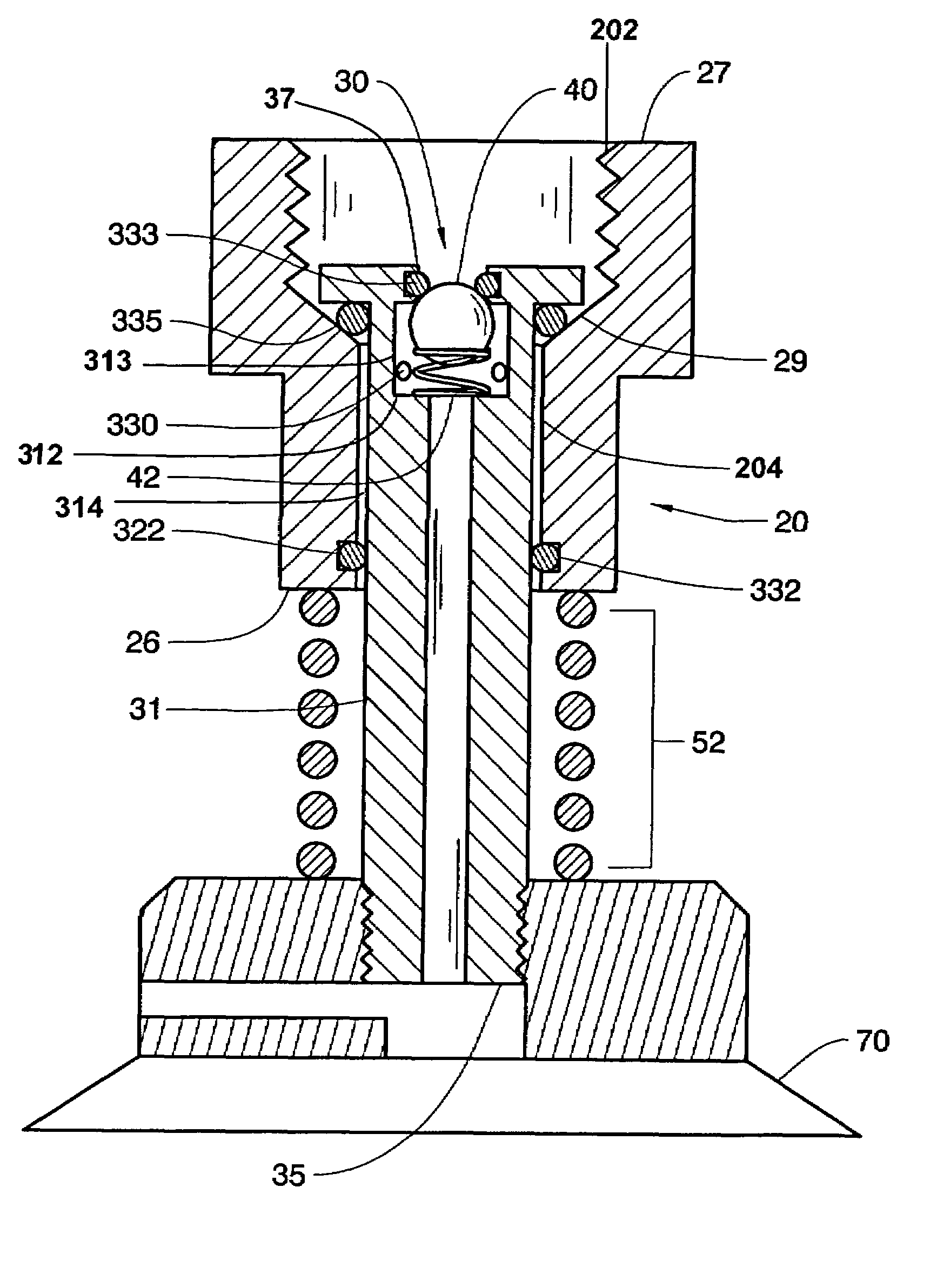
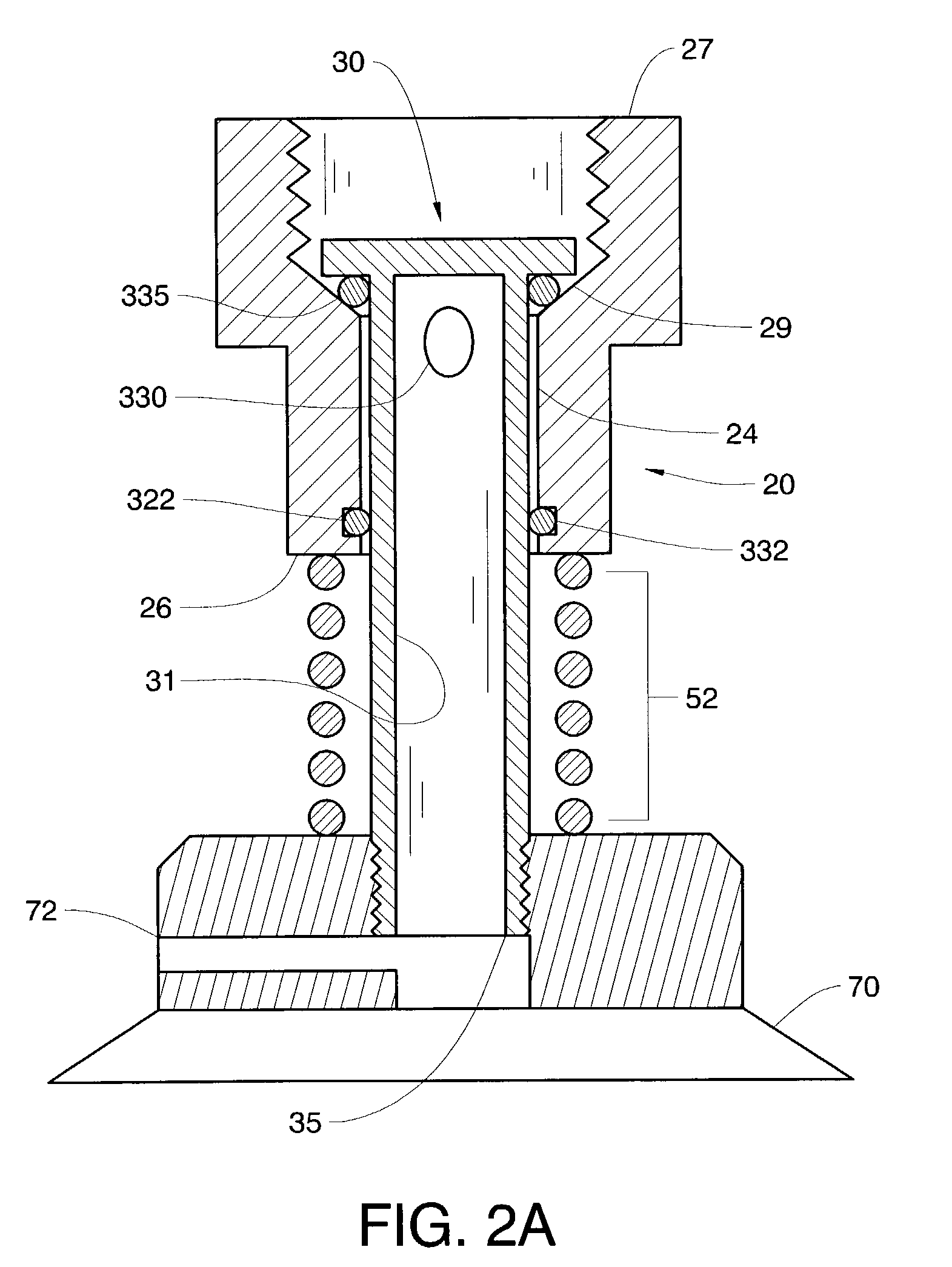
[0024]The biasing force 50 of the second embodiment preferably comprises a spring 52 biased between the valve housing20 and a position fixed relative to the shuttle valve. Ordinarily, the preferred biasing surfaces for the spring 52 comprise the suction head 70 coupled to the chamber shuttle cavity wall 31 and the valve chamber edge 26.

[0025]A first portion of the chamber shuttle cavity wall 31 outer surface travels longitudinally along the valve chamber wall 24, maintaining a fluid flow deterrent and ideally fluid sealing junction between, the valve chamber wall portion delineation edge 29 and the valve chamber edge 26 regardless of the valve state. A second portion of the chamber shuttle cavity wall 31 in which the shuttle cavity aperture 330 exists, is capable of being extended beyond the delineation edge 29 into the first portion of the valve chamber with the larger diameter. When the second portion of shuttle cavity wall 31 is extended beyond the delineation edge 29, it is not ...


PUM


Abstract

A check valve for pick-and-place applications includes a valve housing with a chamber, and a chamber shuttle with a cavity. The chamber shuttle is accessible from outside the chamber and adapted to receive a suction head. The chamber shuttle is adapted to travel within the chamber and establish “valve-open” and “valve-closed” states based upon the contact of the suction head upon the work piece surface. Blow off of the work piece surface is allowed by a fluid flow channel interposed between the suction head and the chamber shuttle cavity.

Description

[0001]This application is a continuation-in-part from earlier filed application Ser. No. 09 / 966,862 filed Sep. 28, 2001 now U.S. Pat. No. 6,517,050.FIELD OF THE INVENTION[0002]The present invention is characterized as a fluid flow valve and is particularly useful in the field of vacuum pressure components used with generated vacuum pressure in pick and place applications.BACKGROUND OF THE INVENTION[0003]Vacuum valves are useful for manipulating a work piece in pick and place applications. An external pressure source is applied to the valve which typically has a suction head attached, the suction head is contacted to the work piece, which is then lifted depending on the porting of vacuum pressure through the valve. Alternate valve designs have evolved to increase the efficiency of the use of vacuum pressure. Two designs include dual flow and tri-flow type valve designs.[0004]Dual flow valves are generally limited to a small fluid flow through an orifice and are preferred in applicati...

Claims


Application Information

Patent Timeline
Patent Type & Authority Patents(United States)
IPC IPC(8): B25J15/06F16K31/383B65G47/91
CPCB65G47/91
Inventor PABST, WILLIAM V.
Owner PARKER INTANGIBLES LLC
Why Eureka
Try Eureka