AI technical title is built by Patsnap AI team. It summarizes the technical point description of the patent document.
a membrane device and stout technology, applied in the direction of mirrors, instruments, mountings, etc., can solve the problems of large pneumatic force required to establish the membrane shape with minimal distortion, frame needs to be of considerable width, and the frame must be heavy and expensive, so as to minimize the distortion of the desired manipulation
Inactive Publication Date: 2008-05-20
SIMMERS DOUGLAS EVAN
View PDF25 Cites 32 Cited by
Summary
Abstract
Description
Claims
Application Information
AI Technical Summary
This helps you quickly interpret patents by identifying the three key elements:
Problems solved by technology
Method used
Benefits of technology
Benefits of technology
"This patent describes an improved device for reflecting, radiating, or receiving electromagnetic radiation, acoustic waves, or other energy forms. The device consists of a membrane stretched across a round frame structure, which is designed to establish a nearly perfect round shape with a circumferential raised portion that provides a near perfect plane for the attachment of the membrane. The frame structure is reinforced by a flat semi-rigid planar surface attached to a circumferential ring or stack of rings, which results in an internal cavity that may be utilized for clearance to permit the deformation of the stretched membrane covering the cavity. The device also includes a unique method of preventing wrinkles that typically form in the periphery of the membrane surface as it is deformed, and a unique method of thermally tensioning the stretched film membrane by applying heat circumferentially around the ring or rings. The technical effects of this invention include improved reflection, reduced distortion, and uniform tensioning of the membrane."
Problems solved by technology
One problem with previous designs is that although the reflective membrane affords an inexpensive method of presenting and manipulating large surfaces for the purpose of directing electromagnetic radiation or other energy, the framework for the membrane must be very strong to withstand the considerable pneumatic forces required to establish the membrane shape with minimal distortion.
These past designs often utilized heavy and expensive frames.
This has the disadvantage in that since both membranes stretch, the frame needs to be of considerable width to prevent the two membranes from touching in the middle when a vacuum is applied.
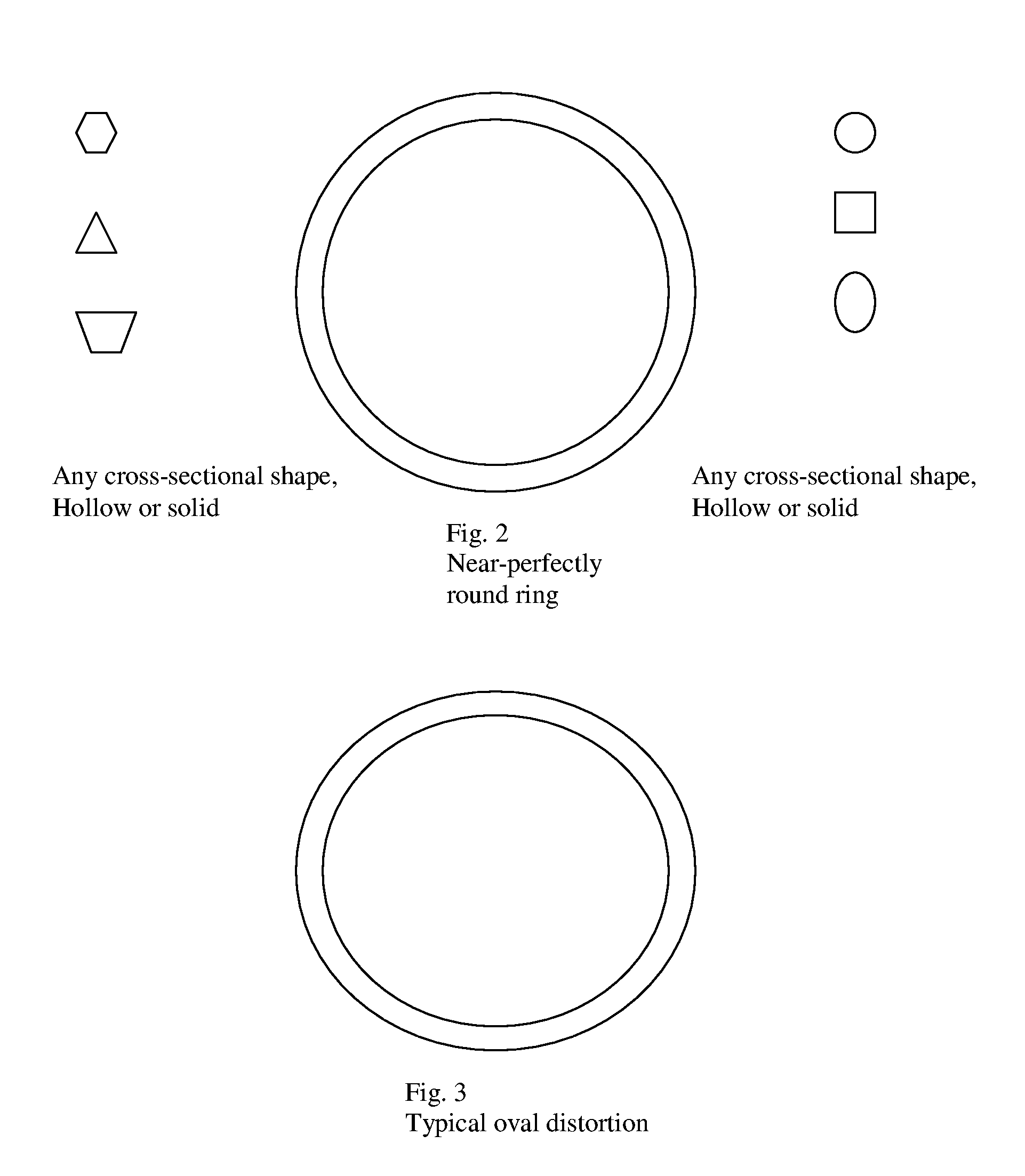
The ovaling stress is non-uniform, and also tends to exacerbate the formation of wrinkles or waves in the membrane surface.
Further, the application of negative or positive pressure inside the proposed structure causes a uniform warpage of the backplane element, increasing the strength of the structure without distortion of the manipulated electromagnetic, acoustic, or other energy.
None of this prior art relates to preventing wrinkles in 360 degree round structure through the use of a circumferential batten.
This problem increases as the size of the structure increases.
Method used
Image
Click on the blue label to locate the original text in one second.
Reading with bidirectional positioning of images and text.
Examples
Embodiment Construction
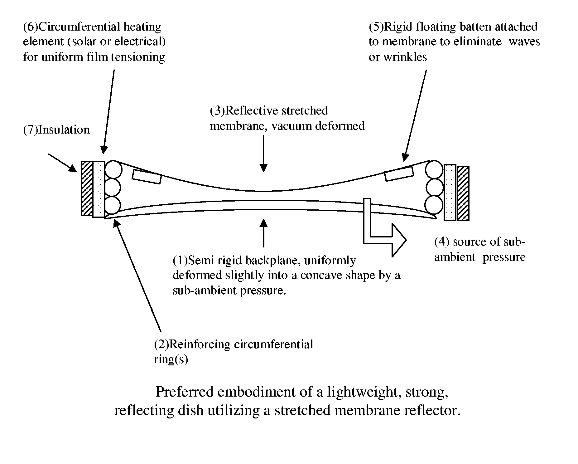
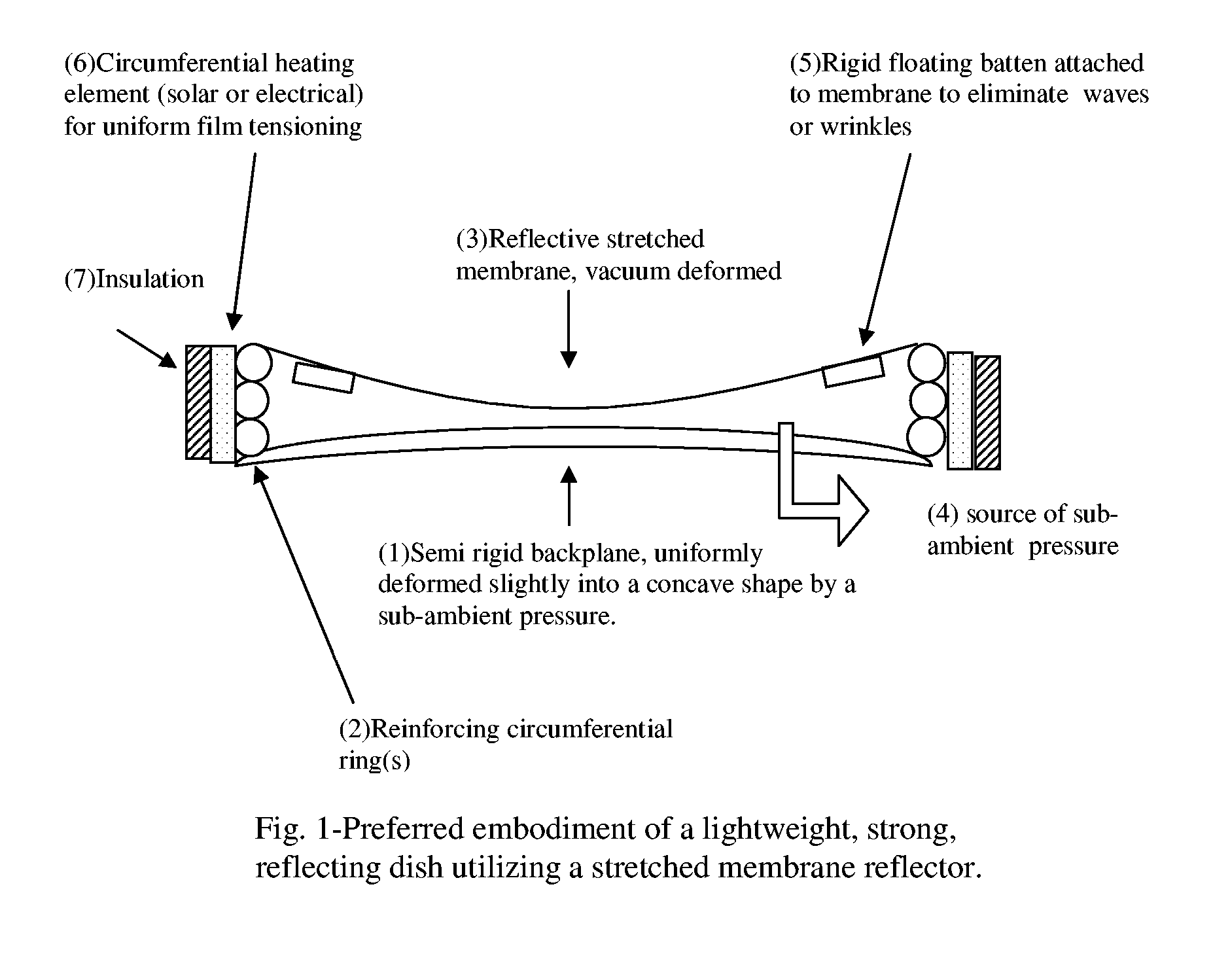
[0064]As shown in the drawings, the preferred embodiment in accordance with the present invention is an improved stretched membrane device for reflecting, radiating, or receiving electromagnetic radiation, acoustic waves, or other energy forms through the use of a membrane stretched across a lightweight, round, frame structure. The preferred embodiment, depicted in FIG. 1 comprises a round frame consisting of (1) a near perfectly round and flat semi rigid foamboard backplane element attached to (2) a stack of near perfectly round circumferential reinforcing ring elements. A reflective membrane element (3) consisting of a non-porous reflective material is stretched across the cavity formed by the structure, and attached to the circumferential ring, thereby forming one wall, and sealing said cavity. A vacuum (4) is placed into to cavity, causing a primary uniform concave deformation of the reflective membrane for the object of manipulating said forms of electromagnetic, acoustic, or o...
PUM
Abstract
An improved device for reflecting, radiating, or receiving electromagnetic radiation, acoustic waves, or other energy forms through the use of a membrane stretched across a lightweight, round, frame structure. A near perfectly round and flat semi-rigid backplane surface (1) and a near perfectly round ring or stack of rings (2) are mutually reinforced, forming a raised circumferential planar surface, and a cavity within. A membrane (3) is attached to the top of the rings, forming one wall of a sealed chamber. A source of sub-ambient pressure (4) is applied to the chamber, causing a primary uniform deformation in the membrane for the purpose of manipulating electromagnetic radiation, acoustic waves, or other energy. The backplane surface also deforms uniformly, increasing the strength of the structure. A flat, rigid floating batten (5) prevents waves or wrinkles from forming in the membrane material. A circumferential heating element (6) and insulation (7) provides tensioning of the membrane by slightly controlling the circumference of the device.
Description
[0001]U.S. Patent Documents:2,300,2511941Flint2,952,1891960Pajes3,031,9281962Kopitko3,056,1311962Mcreary3.610.7381971Bochmann3,687,5241972Martinez3,757,4791973Martinez3,877,1391975Martinez3,880,5001975Kojabashian4,033,6761977Brantley, Jr. et al4,046,4621977Fletcher et al4,068,7771978Humphrey, et al.4,130,2341978Schmidt4,352,1121982Leonhardt, et al4,741,6091988Sallis4,987,8261991Deppert, et al.5,590,4971997Moore5,680,2621997Soliday, et al.5,813,8301998Smith, et al.5,990,8511999Henderson, et al.6,332,6872001Carreras, et al6,716,0172004PapadopoulasBACKGROUND OF THE INVENTION, AND PRIOR ART[0002]Membranes, esp. polymeric membranes, provide an economical method of presenting large surfaces to electromagnetic, acoustic, or other energy, for the purpose of absorbing, reflecting, focusing, or other manipulation of this energy.[0003]Flint (U.S. Pat. No. 2,300,251, 1941) describes fabricating a lens by using two transparent membranes with a clear fluid between. Focal adjustment is made by mec...
Claims
Application Information
Patent Timeline
Application Date:The date an application was filed.
Publication Date:The date a patent or application was officially published.
First Publication Date:The earliest publication date of a patent with the same application number.
Issue Date:Publication date of the patent grant document.
PCT Entry Date:The Entry date of PCT National Phase.
Estimated Expiry Date:The statutory expiry date of a patent right according to the Patent Law, and it is the longest term of protection that the patent right can achieve without the termination of the patent right due to other reasons(Term extension factor has been taken into account ).
Invalid Date:Actual expiry date is based on effective date or publication date of legal transaction data of invalid patent.

