Backlight module having device for fastening lighting units

a backlight module and lighting unit technology, applied in semiconductor devices, lighting and heating apparatus, instruments, etc., can solve the problems of increasing the complexity of the backlight module, the time of assembling, and the cost of manufacturing during the fabrication, so as to reduce the required amount of nuts and bolts, simplify the assembling process, and increase the manufacturing cost

Active Publication Date: 2008-05-20
OPTRONIC SCI LLC
View PDF7 Cites 45 Cited by
  • Summary
  • Abstract
  • Description
  • Claims
  • Application Information

AI Technical Summary

Benefits of technology

[0007]According to the drawbacks described above, the conventional method of fastening the lighting units in the backlight module suffers complexity in assembling and high cost of manufacturing, and therefore, the purpose of the present invention is to provide a fastening device utilized in a backlight module to fasten the lighting units. An object of the present invention is to firmly fasten the lighting units unto the backboard of the backlight module so that the assembling is simplified and the required amount of the nuts and bolts is greatly reduced.
[0008]According to the object described above, the present invention discloses a fastening device utilized in a backlight module to fasten the lighting units and the resultant backlight module. A rigid board partially laps over the adjacent lighting unit or units. The rigid board and the backboard have holes respectively such that bolts are passed through the holes and locked on nuts. Accordingly the rigid board exerts a compressing strength to fasten the adjacent lighting unit or units onto the backboard. In addition to the simplification of the assembling and the decrease of the amount of the nuts and bolts required, the efficiency of thermal dissipation between the lighting units and the backboard is further improved.

Problems solved by technology

However, it increases the complexity of the backlight module, the time of the assembling, and the cost of the producing during the fabricating.

Method used


Image

  • Backlight module having device for fastening lighting units
  • Backlight module having device for fastening lighting units
  • Backlight module having device for fastening lighting units

Examples


Embodiment Construction

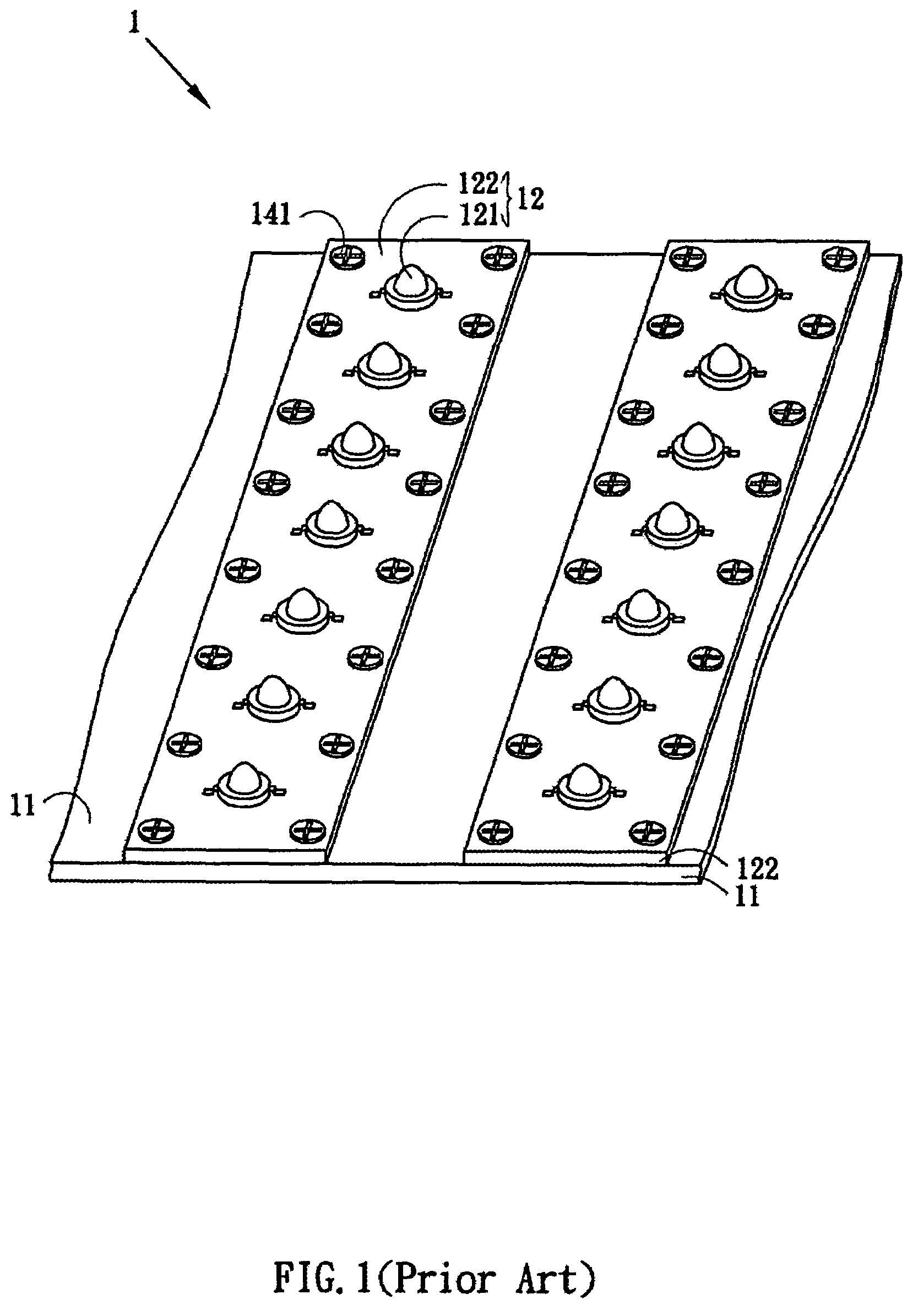
[0017]The following is the detailed description of the present invention, which describes the backlight module and the lighting units, but the detailed structure composition and the operating theory are not discussed. The portions relating to the conventional techniques are briefly described, and the parts of the drawings are not proportionally drafted. While embodiments are discussed, it is not intended to limit the scope of the present invention. Except expressly restricting the amount of the components, it is appreciated that the quantity of the disclosed components may be greater than that disclosed.

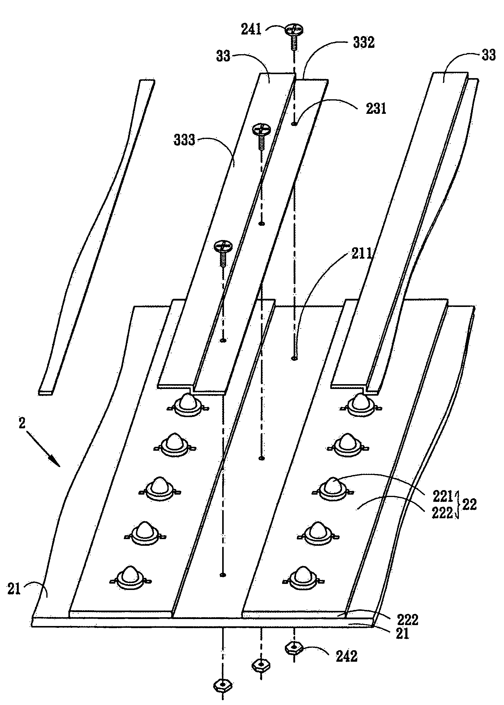
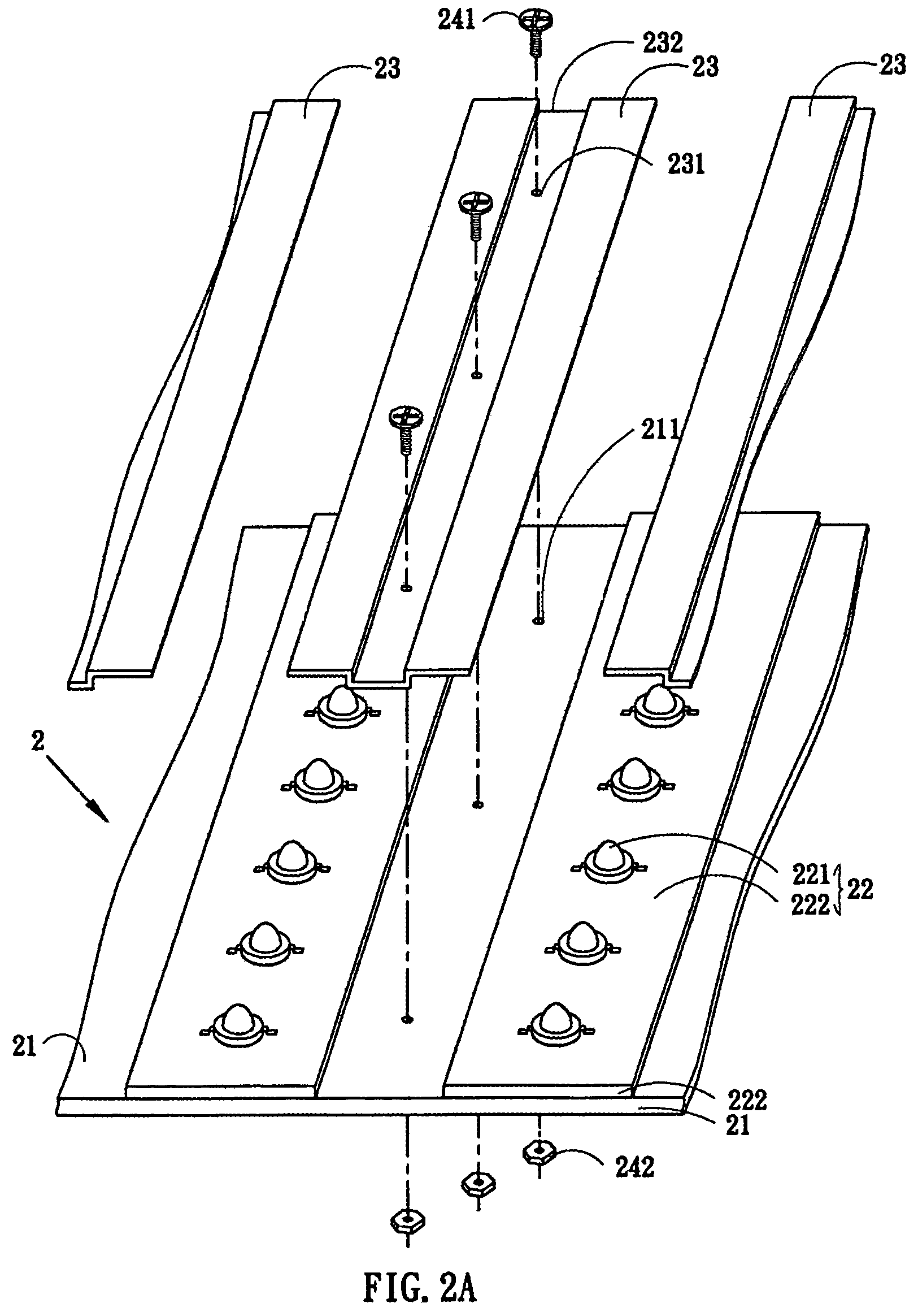
[0018]One of the preferred embodiments of the present invention discloses a backlight module in which the lighting units are fastened. First referring to FIG. 2A, a backlight module 2 is composed of a backboard 21 and a plurality of lighting units 22 arranged in equal space and in parallel to one another on the backboard 21. Each lighting unit 22 comprises a plurality of lighting ele...


PUM


Abstract

A device for fastening the lighting units in a backlight module is provided. A rigid board partially laps over the adjacent lighting unit or units. The rigid board and the backboard have holes respectively such that a bolt is passed through the holes and locked on a nut. Accordingly the rigid board exerts a compressing strength to fasten the adjacent lighting unit or units onto the backboard.

Description

BACKGROUND OF THE INVENTION[0001]1. Field of the Invention[0002]The present invention relates to a fastening device, and more particularly relates to a fastening device utilized in a backlight module to fasten the lighting units.[0003]2. Description of the Prior Art[0004]Referring to FIG. 1, in the prior art, there is a fastening device used to fasten the lighting units 12 of the backlight module 1 within a liquid crystal display. The backlight module 1 composes a backboard 11 and a plurality of lighting units 12 arranged in equal space and in parallel on the backboard 11. Each of the lighting units 12 includes a plurality of lighting elements 121 and an aluminum board 122 carrying the lighting elements 121, wherein the lighting elements 121 are soldered above the aluminum board 122 and connected with the conductive trace (not shown). And, the heat generated by operating the lighting units 12 is dissipated to the backboard 11 through the aluminum board 122.[0005]Still referring to F...

Claims


Application Information

Patent Timeline
Patent Type & Authority Patents(United States)
IPC IPC(8): G01D11/28
CPCF21V29/004F21V29/763F21V29/2212F21V19/001F21Y2101/02G02F1/133603F21Y2115/10
Inventor LIU, PANG-HSUAN
Owner OPTRONIC SCI LLC
Why Eureka
Try Eureka