Assembly group for current measurement

a current measurement and assembly group technology, applied in the direction of magnetic measurement, instruments, measurement devices, etc., can solve the problems of difficult improvement of shielding, inability to integrate both hall elements on a single semiconductor chip, and often too little shielding efficiency, etc., to achieve high bandwidth, small overall size, and robust against mounting tolerances

Active Publication Date: 2008-05-20
MELEXIS TECH NV
View PDF26 Cites 27 Cited by
  • Summary
  • Abstract
  • Description
  • Claims
  • Application Information

AI Technical Summary

Benefits of technology

[0004]The object of the invention is to develop a solution for current measurement providing a small overall size, that is robust against mounting tolerances, external interference fields and temperature changes, has a high bandwidth and enables a simple and economic assembly.
[0014]The measuring element is very small. The distance between the two magnetic field sensors lies in a range of about 1 bis 3 millimeters. This reduces the sensitivity of the measuring element to an external inhomogeneous magnetic field.
[0015]The mounting of the measuring element on the conductor plate is very simple. It is simply glued at the right position onto the conductor plate. The position accuracy is not very critical.
[0017]By the realization of the whole electronic circuit and of all magnetic field sensitive sensing elements on a single semiconductor chip the variation of the properties of the magnetic field sensitive sensing elements are reduced, the magnetic field sensitive sensing elements always have approximately the same temperature and the distance between the two magnetic field sensors is fix given and remains constant during the lifetime.

Problems solved by technology

Because such shields are often too little efficient and an improvement of the shielding is difficult and, if at all, only with high effort devices with a u- or s-shaped conductor and two Hall elements have been developed, wherein the magnetic field created by the current at the locations of the two Hall elements points in directions running opposite to each other.
Because the Hall elements have to be placed within the cuts of the u- or s-shaped conductor it is not possible to integrate both Hall elements on a single semiconductor chip.
For this reason the assembly of the individual components is extensive and complicated.

Method used


Image

  • Assembly group for current measurement
  • Assembly group for current measurement
  • Assembly group for current measurement

Examples


Embodiment Construction

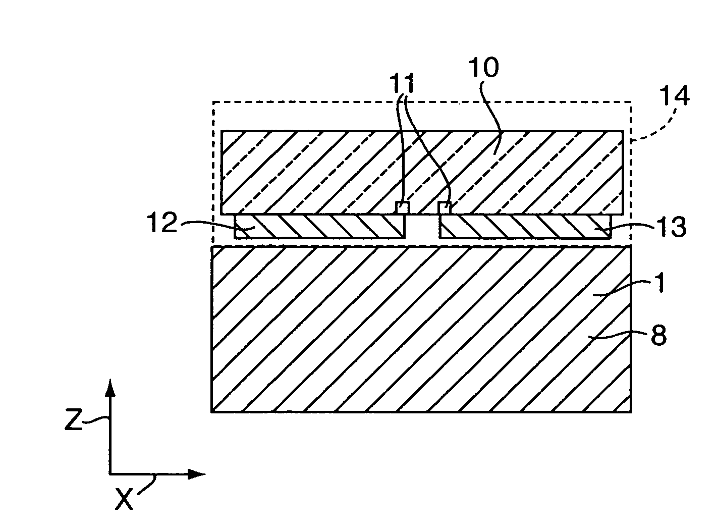
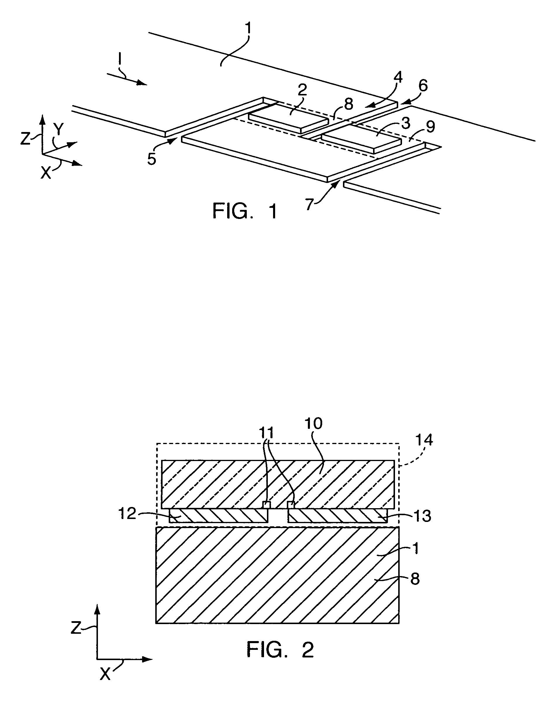
[0027]FIG. 1 shows a schematical, three-dimensional representation of an assembly group for current measurement according to the invention, that is designed for example for a working range from 0 to 200 A. The assembly group comprises a conductor plate 1 in the form of a flat conductor, through which the current I to be measured flows, and a difference sensor 4 formed of two magnetic field sensors 2 and 3. The conductor plate 1 contains three cuts 5, 6 and 7 arranged orthogonally to its longitudinal direction, here the x-direction, so that a first and second conductor section 8 and 9 are formed such that the current direction in the second conductor section 9 runs opposite to the current direction in the first conductor section 8. The borders of the two conductor sections 8 and 9 are illustrated by means of dashed lines. The first magnetic field sensor 2 is arranged on the first conductor section 8 and the second magnetic field sensor 3 is arranged on the second conductor section 9....


PUM


Abstract

An assembly group for current measurement comprises a conductor plate with three cuts and a measuring element placed on the conductor plate that has a difference sensor formed from two magnetic field sensors. By means of the three cuts a first and a second conductor section are formed in the conductor plate, wherein the current direction in the second conductor section runs opposite to the current direction in the first conductor section. The first magnetic field sensor is located above the first conductor section and the second magnetic field sensor is located above the second conductor section. The magnetic field sensors are sensitive to a magnetic field that runs parallel to the surface of the conductor plate and orthogonal to the current direction in the two conductor sections.

Description

PRIORITY CLAIM[0001]Applicant hereby claims foreign priority under 35 U.S.C § 119 from Swiss Application No. 1639 / 05 filed on Oct. 8, 2005, the disclosure of which is herein incorporated by reference.FIELD OF THE INVENTION[0002]The invention concerns an assembly group for current measurement.BACKGROUND OF THE INVENTION[0003]Touchless measurement of current with Hall elements is used for many applications, for example in electricity meters or for the measurement of the current fed to or taken from a battery. The Hall element measures the magnetic field created by the current. In order to reduce the influence of magnetic interference fields that originate from other magnetic field sources shields of ferromagnetic material are used in many cases. Because such shields are often too little efficient and an improvement of the shielding is difficult and, if at all, only with high effort devices with a u- or s-shaped conductor and two Hall elements have been developed, wherein the magnetic ...

Claims


Application Information

Patent Timeline
Patent Type & Authority Patents(United States)
IPC IPC(8): G01R15/20
CPCG01R15/207G01R15/202
Inventor RACZ, ROBERTHUBER, SAMUEL
Owner MELEXIS TECH NV
Why Eureka
Try Eureka