Method and apparatus for optimizing the viewing distance of a lenticular stereogram

a lenticular stereogram and viewing distance technology, applied in the field of three-dimensional stereoscopic print images, can solve the problems of inability to precisely juxtapose, lenticular stereograms have a limited range of points at which they can be viewed without degradation, and inhibit the medium from becoming more pervasive, so as to improve the viewing zone and increase the viewing zone

Inactive Publication Date: 2008-05-20
LEDOR LLC +1
View PDF2 Cites 116 Cited by
  • Summary
  • Abstract
  • Description
  • Claims
  • Application Information

AI Technical Summary

Benefits of technology

[0007]The present invention is a simple method for increasing the viewing zone of a stereoscopic image that may be a photographic print, a projected or computer-generated image, or any other type of graphical image. The viewing zone is improved by determining the optimum column width for the image columns of the stereoscopic image. The optimum column width provides optical alignment for each column with its corresponding lenticule for a specified viewing position. The optimum column width may be determined empirically with a series of test images. Once determined, stereoscopic images having the optimum column width can be produced using an interdigitation program.

Problems solved by technology

Although the art of making lenticular stereograms is continuing to advance, a number of persistent problems remain which inhibit the medium from becoming more pervasive.
In particular, lenticular stereograms have a limited range of points at which they can be viewed without degradation of the three-dimensional image due to the parallax effect.
The parallax effect occurs at acute viewing angles and creates a lack of precise juxtaposition between the columnar structured image and the associated columnar lenticules.
The lack of juxtaposition occurs because at a highly acute angle, the focal point of the lenticule is not properly on the associated print column and an inaccurate columnar image is viewed.
Also, the lenticular screen is imposed on a curved structure with varying lenticule widths that is very difficult to manufacture.
Thus, none of these references provides a simple solution for maximizing the viewing zone of a lenticular stereogram.

Method used


Image

  • Method and apparatus for optimizing the viewing distance of a lenticular stereogram
  • Method and apparatus for optimizing the viewing distance of a lenticular stereogram
  • Method and apparatus for optimizing the viewing distance of a lenticular stereogram

Examples


Embodiment Construction

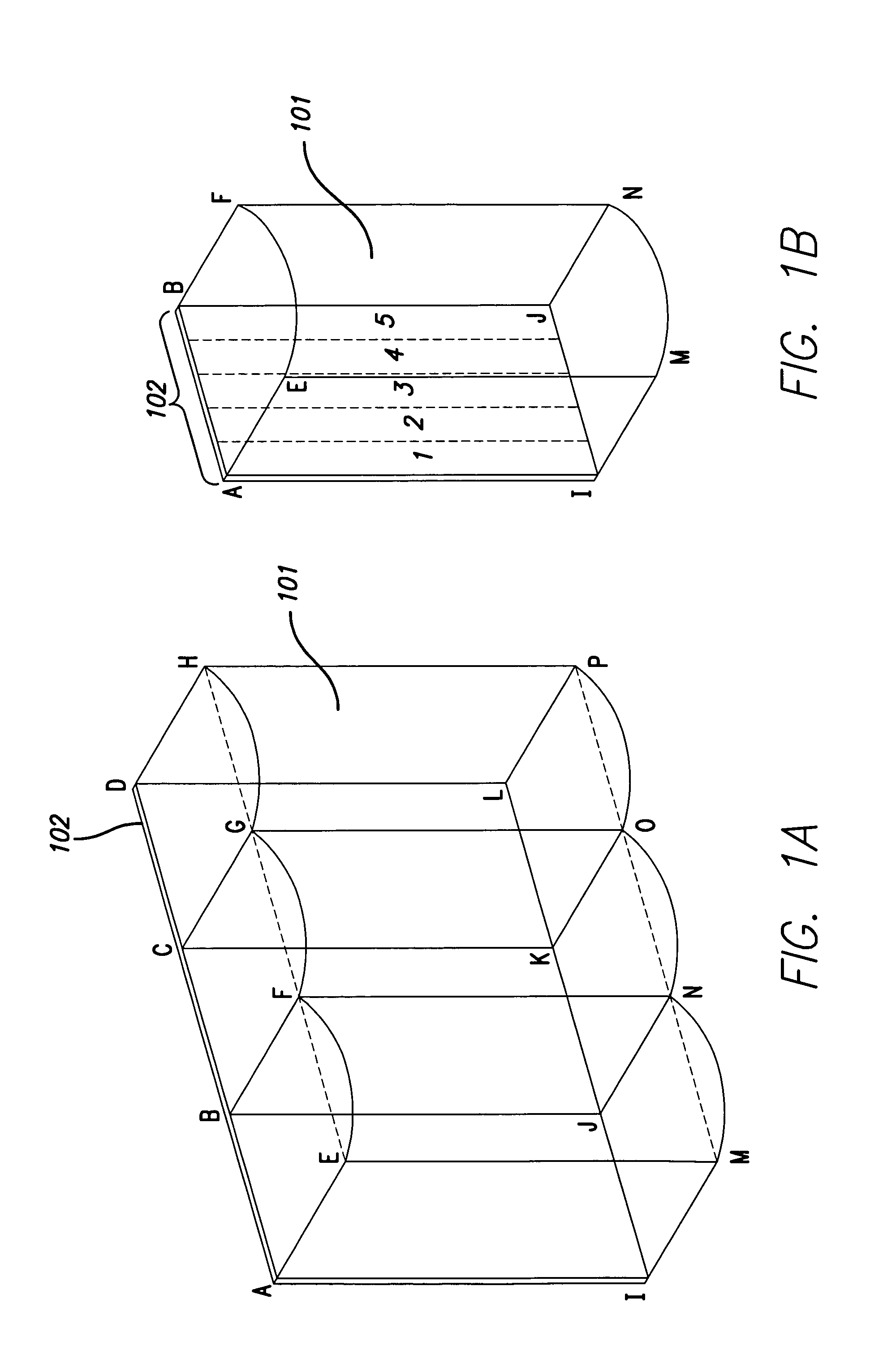
[0026]Referring to FIG. 1A, a portion of a lenticular screen 101 and associated print 102 is illustrated. The term “print” is used broadly to signify any well-known displays, such as a rear-projected display, a photographic print, a photo-mechanically-reproduced print, or an electronic display screen, as well as combinations of these known displays. The print 102 is fixed in intimate juxtaposition with the lenticular screen 101 such that two parallel planes are referenced: the plane of print 102 is defined by points ADLI and the reference plane of the lenticules is defined by points EHPM. The lenticules are individual cylindrical lenses, EFNM, FGON and GHPO having cylindrical surfaces illustrated as equal radius arcs EF, FG and GH, and corresponding arcs MN, NO and OP respectively. The lenticule screen is overlaid on top of reference plane EHPM and each lenticule is optically aligned in intimate juxtaposition with a corresponding rectangular print area on print 102 to provide differ...


PUM


Abstract

A method and apparatus for optimizing viewing distance for a stereogram system. In a stereogram, an image is held in close juxtaposition with a lenticular screen. In the invention, a data store is used to store optimum pitch values for specified viewing distances. An interdigitation program then acts on the table values and creates a mapping of interdigitated views for each viewing distance. The user can then select or specify a desired viewing distance, and the optimum mapping of views is automatically chosen for display.

Description

FIELD OF THE INVENTION[0001]This invention relates to three-dimensional stereoscopic print images, also known as lenticular stereograms or parallax panoramagrams, and more particularly, to a method and apparatus for increasing the viewing zone of images in lenticular stereograms.BACKGROUND OF THE INVENTION[0002]Lenticular stereograms have been used for many years to display a true three-dimensional stereoscopic image without the need for the observer to wear special selection devices that selectively permit the left eye and right eye to see different images. Selection devices are typically eyeglasses that are colored (red / green) or polarized so that a left image and a right image can be viewed from one source. The lenticular stereogram is made by photomechanical reproduction and most commonly used for trading cards, picture postcards, product displays, and the like. By incorporating a cylindrical lenticular screen that has a corduroy-like surface over a properly encoded image print,...

Claims


Application Information

Patent Timeline
Patent Type & Authority Patents(United States)
IPC IPC(8): G02B27/22H04N13/04H04N9/47G02B30/27
CPCG02B27/2214G02B30/27
Inventor LIPTON, LENNYMCKEE, JR., WILLIAM JAMESFELDMAN, MARK H.
Owner LEDOR LLC
Why Eureka
Try Eureka