Method and system for checking rotate, shift and sign extension functions using a modulo function

a technology of modulo function and function, applied in the field of error detection, can solve problems such as inherent inefficiency in duplication of functions, inability to tolerate errors in microprocessors, and inability to detect errors in shift, rotate, and sign extension functions

Inactive Publication Date: 2008-05-20
INT BUSINESS MASCH CORP
View PDF5 Cites 6 Cited by
  • Summary
  • Abstract
  • Description
  • Claims
  • Application Information

AI Technical Summary

Benefits of technology

[0012]All objects, features, and advantages of the present invention will become apparent in the following detailed written description.

Problems solved by technology

Whether the impact of errors would be measured in human lives or in mere dollars and cents, consumers of microprocessors have lost tolerance for error-prone results.
Consumers will not tolerate, by way of example, miscalculations on the floor of the stock exchange, in the medical devices that support human life, or in the computers that control their automobiles.
As can be easily imagined, there is an inherent inefficiency in duplication of a function.
Simply stated, the duplication of a function doubles the circuitry necessary to perform a given calculation, resulting in increased design complexity and chip size.
Fabrication costs, design time, power consumption, and the potential for errors all increase with the amount of circuitry on a chip.
The modulo function has proven useful for streamlining error-checking operations, but its applicability conventionally is limited by the methods that are conventionally used to calculate it.
Accordingly, conventional modulo / residue checking cannot be used to check rotate, sign extend, or shift functions, because their operands are discarded or altered in the course of the underlying operation.
Storage of the operands of a function for later calculation of a modulo check would involve a waste of resources in terms of complexity, power consumption, and cost.
Thus, storage of operands would cause problems unacceptably similar to the problems presented by duplicating a function and comparing the two results.

Method used


Image

  • Method and system for checking rotate, shift and sign extension functions using a modulo function
  • Method and system for checking rotate, shift and sign extension functions using a modulo function
  • Method and system for checking rotate, shift and sign extension functions using a modulo function

Examples


Embodiment Construction

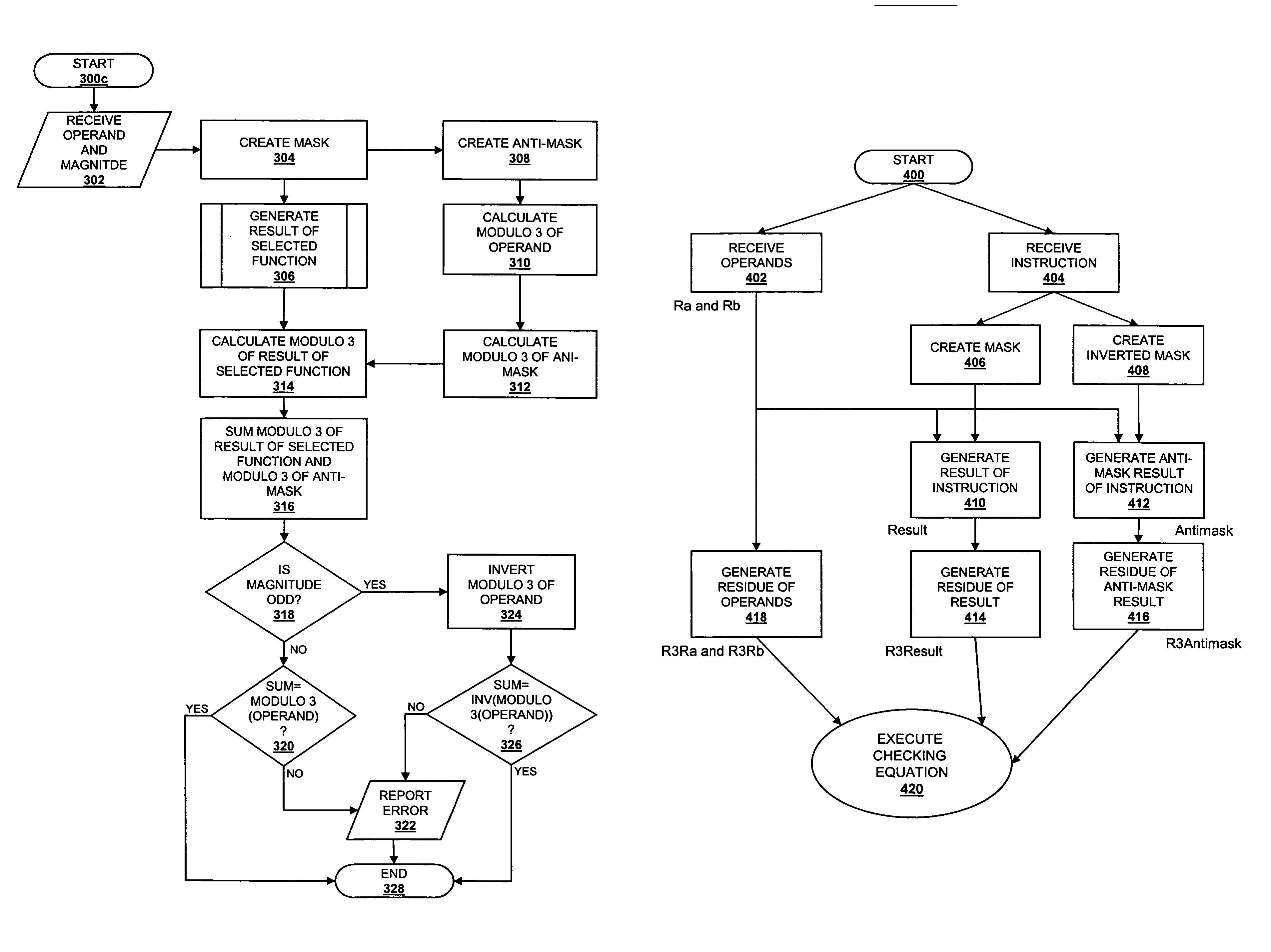
[0018]A preferred embodiment of the present invention provides for the error-checking of circuits for performing rotate, sign extend, and shift functions within a binary processor by employing the mathematical relationship of residue. Advantages of the preferred embodiment include the ability to expose the failure of a circuit or circuit component without resorting to duplication of a function and comparison of results.

[0019]The checking methodology of a preferred embodiment includes the calculation of an antimask term. An antimask value contains information that is not needed in producing the result of a function but is needed to insure all data that went into executing the instruction is preserved, without resorting to the more resource intensive storage of operands. Without an antimask term, conventional modulo-based error checking is not preferable for rotate, sign extend, and shift functions because conventional modulo-based error checking requires that an operand be preserved ...


PUM


Abstract

A method of discovering a fault in a circuit is disclosed. The method comprises generating a first result of a selected function by performing the selected function on an operand, wherein the selected function employs a mask. Once the function is performed, an antimask of the mask is created, and the modulo of the antimask is calculated. A modulo function of the first result of the selected function is calculated to obtain a third result. A modulo of the operand is then calculated to obtain a fourth result, and a second function is then performed on the second result and the third result to obtain a fifth result. In response to comparing the fifth result to the fourth result, a signal is propagated to indicate a fault in the circuit.

Description

BACKGROUND OF THE INVENTION[0001]1. Technical Field[0002]The present invention relates in general to an improved method of error detection, and, in particular, to an improved method of discovering errors in a logical function. Still more particularly, the present invention relates to an improved method for discovering errors in shift, rotate, and sign extension functions.[0003]2. Description of the Related Art[0004]With the increasing penetration of microprocessor-based systems into every facet of human activity, demands have increased on the microprocessor development and production community to produce systems that are free from data corruption. Microprocessors have become involved in the performance of a vast array of critical functions, and the involvement of microprocessors in the important tasks of daily life has heightened the expectation of reliability of calculative results. Whether the impact of errors would be measured in human lives or in mere dollars and cents, consumer...

Claims


Application Information

Patent Timeline
Patent Type & Authority Patents(United States)
IPC IPC(8): G06F11/10G06F7/38G06F11/00G06F11/22G06F11/267
CPCG06F11/2226
Inventor BUSABA, FADI Y.POWELL, LAWRENCE JOSEPHSCHMOOKLER, MARTIN STANLEYVADEN, MICHAEL THOMASWEBBER, DAVID ALLAN
Owner INT BUSINESS MASCH CORP
Why Eureka
Try Eureka