Software change modeling for network devices

a network device and software change technology, applied in the field of software change modeling for network devices, can solve the problems of interrupting any computer's tasks, unacceptable restarting of the computer, complex and perplexing problems, etc., and achieves the effect of broad flexibility and easy update of all nodes

Inactive Publication Date: 2008-05-20
CISCO TECH INC
View PDF49 Cites 92 Cited by
  • Summary
  • Abstract
  • Description
  • Claims
  • Application Information

AI Technical Summary

Problems solved by technology

The issue of how a computer system obtains its operating software and the effects upon the overall networked system by the loading of new operating software on the computer system has been a complex and perplexing problem.
This requires that all processes on the computer be halted and restarted, thereby interrupting any tasks that the computer may be performing.
However, if a multi-node system is purposed to perform an uninterruptible operation, such as managing telecommunications links, the restarting of a computer is not acceptable because a telecommunications link will be disturbed.
The computer must also be running an operational version of Windows to be able to communicate with the server, therefore, a new computer is useless until a copy of Windows is installed by a user.
Further, the reliance on a human being to perform software selection and initiate software downloads is not desirable in stand-alone systems.
This approach worked well for homogeneous systems, but could not work with heterogeneous systems.
However, the drawback to this approach is that it requires that an identical program be distributed to all of the networked computers and it does not contemplate the problems associated with a heterogeneous set of computers that require individual software component updates, nor the management of such components.

Method used


Image

  • Software change modeling for network devices
  • Software change modeling for network devices
  • Software change modeling for network devices

Examples


Embodiment Construction

[0026]A method and apparatus for software change modeling for network devices is described. In the following description, for the purposes of explanation, numerous specific details are set forth in order to provide a thorough understanding of the present invention. It will be apparent, however, to one skilled in the art that the present invention may be practiced without these specific details. In other instances, well-known structures and devices are shown in block diagram form in order to avoid unnecessarily obscuring the present invention.

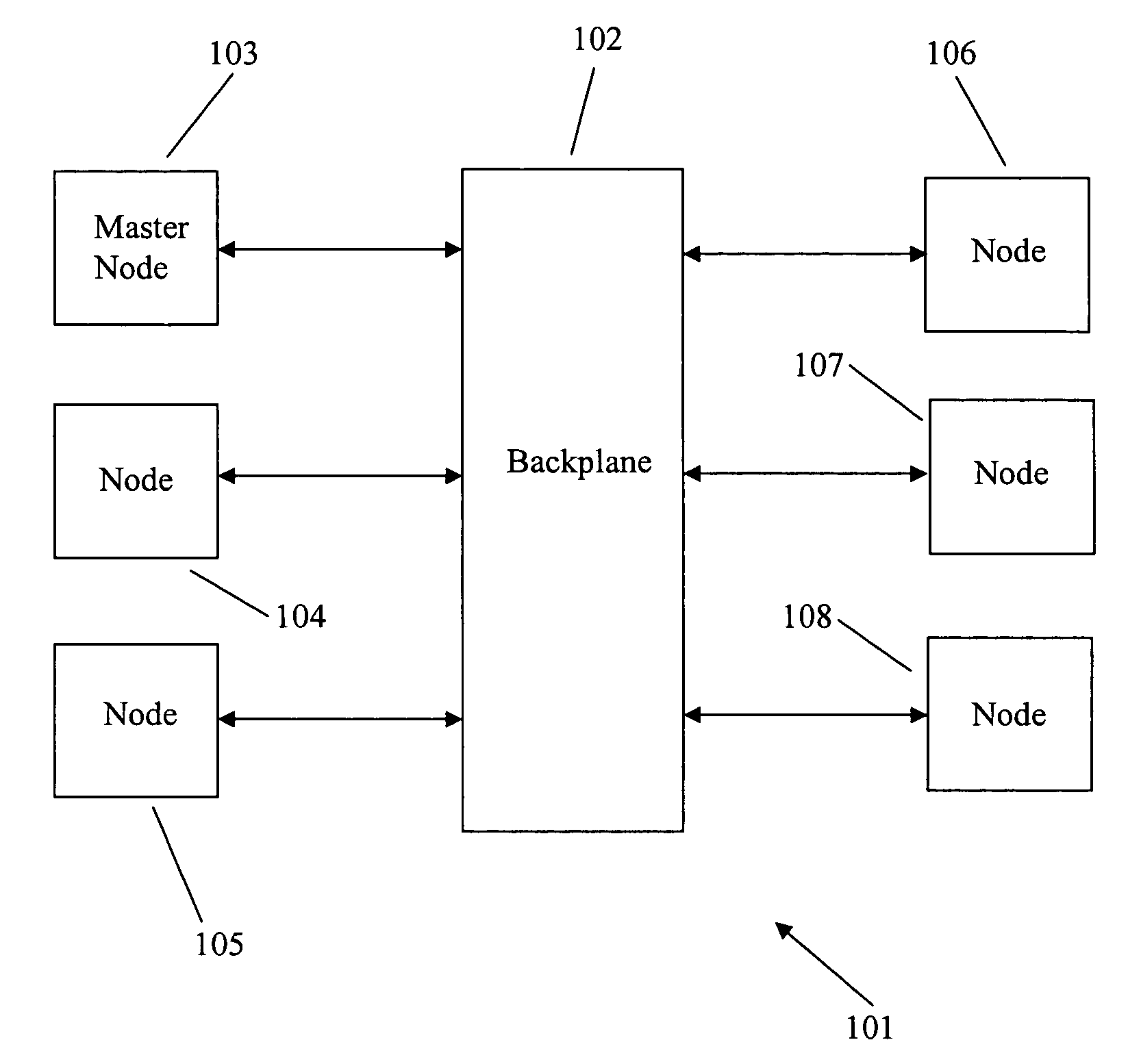
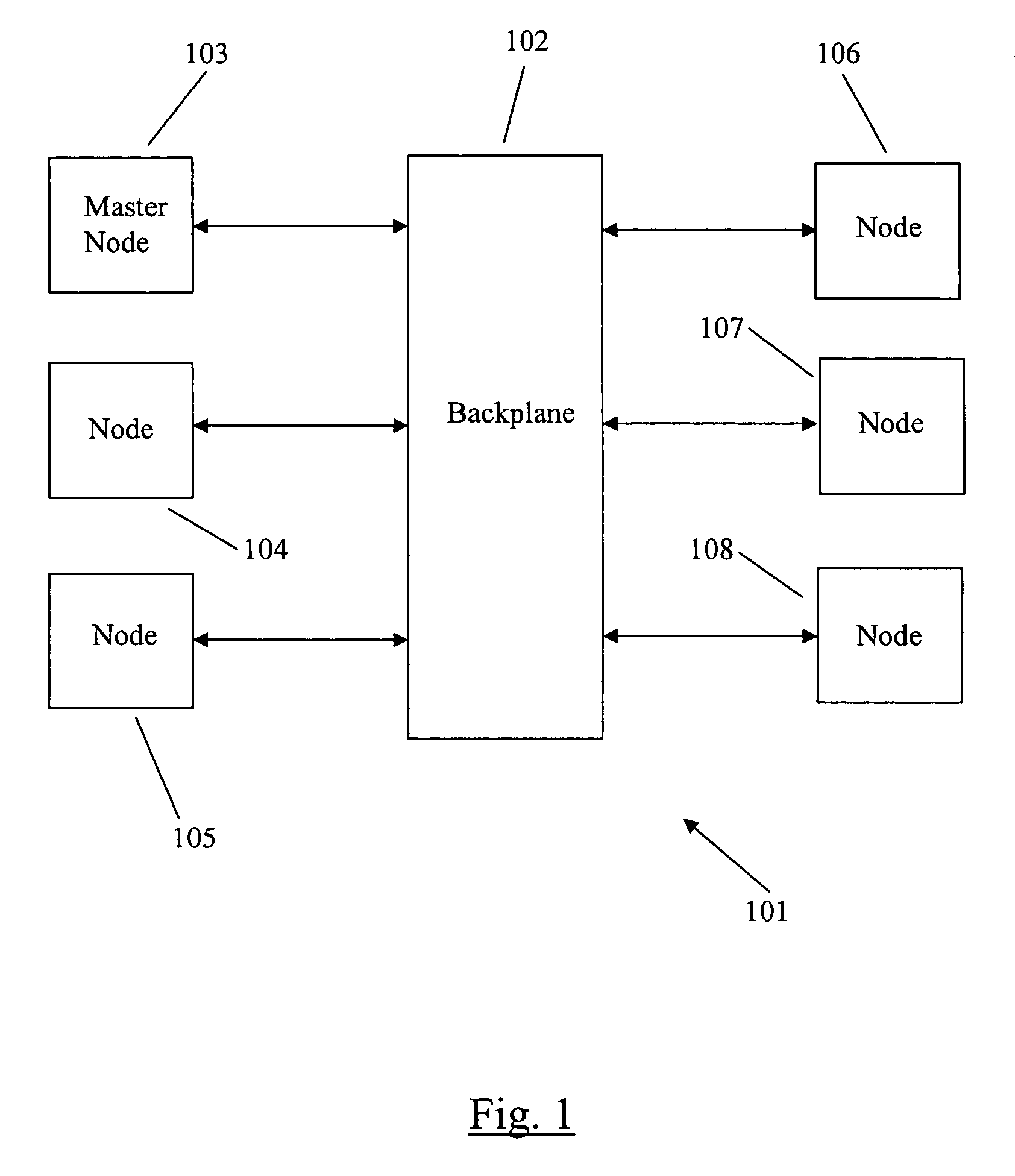
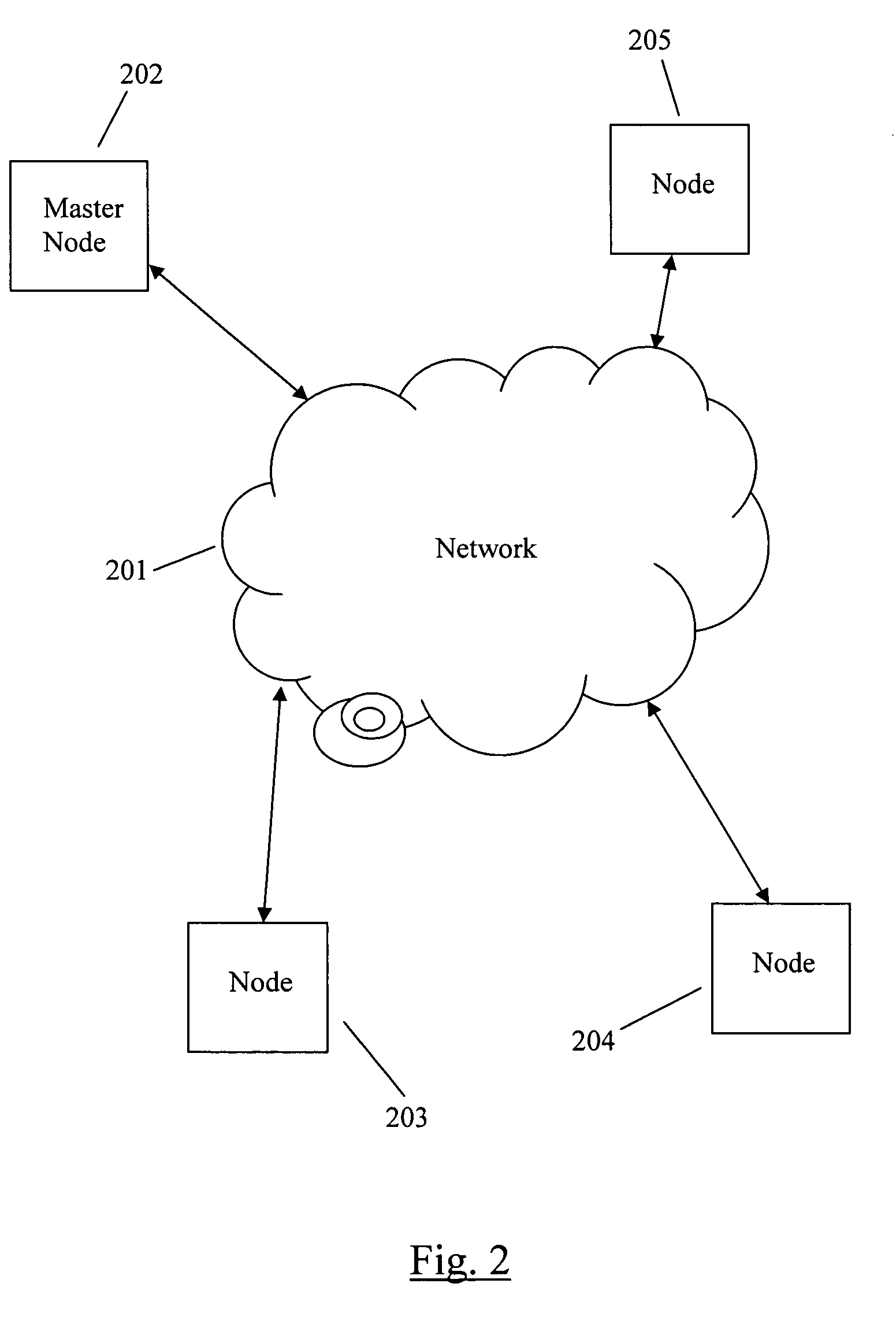
[0027]Embodiments are described herein according to the following outline:[0028]1.0 General Overview[0029]2.0 Structural and Functional Description[0030]2.1 Dynamic Loading, Installation, and Activation of Software Packages in a Router System[0031]2.2 Dynamic Loading, Installation, and Activation of Software Packages in a Networked Computer System[0032]2.3 Master Node Interaction[0033]2.4 Software Package Breakdown and Loading[0034]2.5 Task Anal...


PUM


Abstract

A method for software change modeling for network devices provides dynamic (on the device) and static (computer) change modeling. The same source code and libraries are used for both modeling applications, allowing a user to see the impact of activating or deactivating specific software modules without affecting the actual node. A master node passes a node the identity of the software package(s) to be updated and the dependencies. The node notifies its running processes about the update. If any of the processes determine that the update will degrade or have a negative impact on the operation of the node, it returns a veto to the node which sends a list of the processes that are impacted along with the reasons why to the master node.

Description

FIELD OF THE INVENTION[0001]The present invention generally relates to the management, loading, and installation of select software modules onto networked nodes. The invention relates more specifically to a method and apparatus for the modeling of software packages for a distributed networking device.BACKGROUND OF THE INVENTION[0002]The approaches described in this section could be pursued, but are not necessarily approaches that have been previously conceived or pursued. Therefore, unless otherwise indicated herein, the approaches described in this section are not prior art to the claims in this application and are not admitted to be prior art by inclusion in this section.[0003]Networked computer systems have evolved over the years from simple serially connected computer systems to massively networked computer systems connected via large intranets and the Internet. During this evolution, many different concepts were developed to manage and load core operating software for client co...

Claims


Application Information

Patent Timeline
Patent Type & Authority Patents(United States)
IPC IPC(8): G06F9/44
CPCG06F8/67G06F9/4416G06F9/44521G06F9/45537G06F8/656
Inventor KAKUMANI, BADARIDARLING, GLENBALINT, MATTHEW
Owner CISCO TECH INC
Why Eureka
Try Eureka