Pressure sensor method and apparatus

a technology of pressure sensor and transducer, applied in the direction of instruments, fluid pressure measurement by mechanical elements, measurement devices, etc., can solve the problems of high package size, high accuracy and repeatability, and design operation need to be reliable, so as to facilitate understanding

Active Publication Date: 2008-05-27
HONEYWELL INT INC
View PDF11 Cites 46 Cited by
  • Summary
  • Abstract
  • Description
  • Claims
  • Application Information

AI Technical Summary

Benefits of technology

[0011]The following summary is provided to facilitate an understanding of some of the innovative features unique to the embodiments disclosed and is not intended to be ...

Problems solved by technology

The operational environments in which pressure sensors are required to operate in these applications with high accuracy and repeatability can be very demanding.
One of the problems with the prior art configurations illustrated in FIGS. 1-4 is that such designs need to operate reliably under the conditions described earlier and with the use of attach materials which have high strength and chemical resistance.
The rigid mounting of a stress sensitive die (e.g., pressure transducer), for example, onto a PCB where there...

Method used


Image

  • Pressure sensor method and apparatus
  • Pressure sensor method and apparatus
  • Pressure sensor method and apparatus

Examples


Embodiment Construction

[0022]The particular values and configurations discussed in these non-limiting examples can be varied and are cited merely to illustrate at least one embodiment and are not intended to limit the scope thereof.

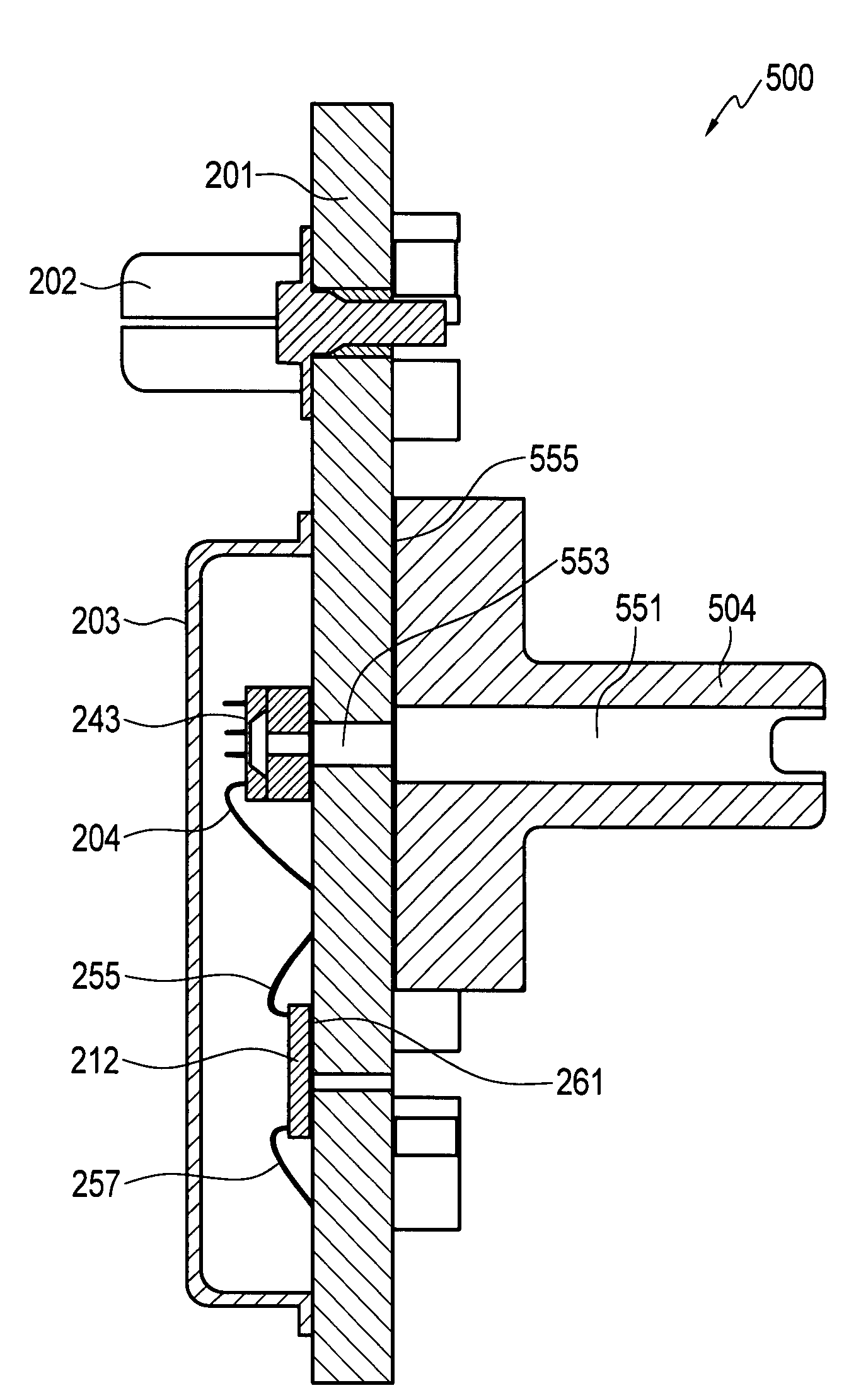
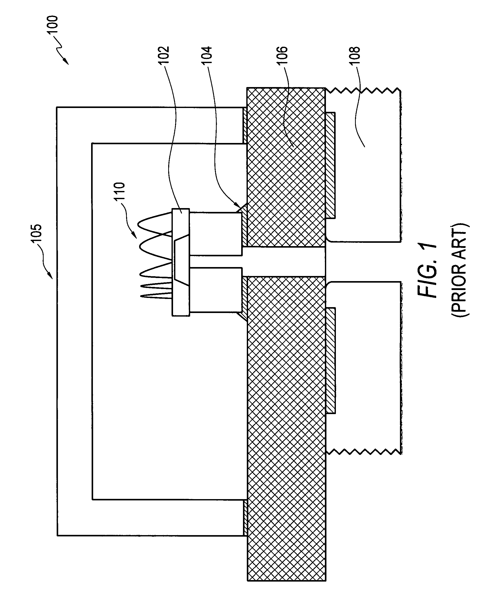
[0023]Referring now to the drawings and in particular to FIG. 5, a bond-side view of a pressure sensor apparatus 500 is illustrated, which can be implemented in accordance with a preferred embodiment. Additionally, FIG. 6 illustrates a side sectional view of the pressure sensor apparatus 500 depicted in FIG. 5 in accordance with a preferred embodiment. Note that in FIGS. 5-6, identical or similar parts or elements are generally indicated by identical reference numerals. Additionally, FIGS. 5-6 illustrate components which are also depicted in the prior art illustrations of FIGS. 2-4. It can be appreciated, however, that such components are shown in FIGS. 5-6 in order to demonstrate the improvements and differences between apparatus 500 and that of the prior art apparatus 200.

[00...


PUM


Abstract

A pressure sensor apparatus and a method of forming the same. A substrate (e.g., PCB) can be provided that includes a top side and a bottom side. A pressure transducer can be directly bonded to the top side of the substrate, wherein the substrate comprises substrate walls forming a plated through-hole that allows for the passage of a sensed media to contact a back side of the pressure transducer. Thereafter, a metal carrier with an integral port is bonded to the bottom side of the substrate, thereby forming a chip-on-board pressure sensor in which the need for a plating or coating to allow adhesion between the pressure transducer and the metal carrier is eliminated. The pressure transducer may comprise, for example, silicon or silicon bonded to glass. The metal carrier can be provided with a feature that mates with a valve such as a Schrader valve.

Description

CROSS-REFERENCE TO RELATED PATENT APPLICATION[0001]This patent application claims priority to U.S. Provisional Patent Application Ser. No. 60 / 911,554, filed on Apr. 13, 2007, and which is incorporated herein by reference in its entirety.TECHNICAL FIELD[0002]Embodiments are generally related to pressure sensors and transducers. Embodiments are also related to Chip-on-Board components and configurations. Embodiments are additionally related to chip-on-board pressure sensor packages.BACKGROUND OF THE INVENTION[0003]Many processes and devices have been used in the field of pressure sensing. Pressure sensors are generally used and deployed wherever a need for monitoring and responding to pressure changes is necessary. Pressure sensors are commonly used in a variety of automotive, aerospace, commercial, industrial, and consumer applications.[0004]The operational environments in which pressure sensors are required to operate in these applications with high accuracy and repeatability can be...

Claims


Application Information

Patent Timeline
IPC IPC(8): G01L7/00
CPCG01L19/147G01L19/148H01L2224/48091H01L2224/49171H01L2224/73265H01L2924/00014
Inventor LAMB, WAYNE A.RICKS, LAMAR F.BRADLEY, ALISTAIR D.
Owner HONEYWELL INT INC
Why Eureka
Try Eureka