Prosthetic cardiac value and method for making same

a technology of prosthetic valves and valves, applied in the field of prosthetic valves, can solve the problems of occlusion of the conduit, thrombosis and platelet deposition, and the severity of congenital valve abnormalities,

Inactive Publication Date: 2008-05-27
THE CLEVELAND CLINIC FOUND
View PDF44 Cites 268 Cited by
  • Summary
  • Abstract
  • Description
  • Claims
  • Application Information

AI Technical Summary

Problems solved by technology

Eventually, the thrombus can severely restrict blood flow through the conduit defined by the endovascular prosthesis and, if left untreated, can completely occlude the conduit.
Additionally, thrombosis and platelet deposition may occur as a result of irregularities on the inner surface of a cardiovascular prosthesis.
Congenital valve abnormalities may be so severe that emergency surgery is required within the first few hours of life, or they may be well-tolerated for many years only to develop a life-threatening problem in an elderly patient.
The two major problems that can develop with heart valves are stenosis, in which a valve does not open properly, and insufficiency (also called regurgitation), in which a valve does not close properly.
Stenosis and insufficiency may occur concomitantly in the same valve or in different valves.
Both of these abnormalities increase the workload and stress placed on the heart.
If this occurs on the valves of the left side (i.e., the systemic circulation side) of the heart, embolization results in sudden loss of the blood supply to the affected body organ and immediate malfunction of that organ.
Their main disadvantage is that they require the patient to take systemic anticoagulation drugs for the rest of his or her life, because of the propensity of mechanical valves to cause blood clots to form on them.
The major disadvantage of tissue valves is that they lack the long-term durability of mechanical valves.
It should be noted that the structure associated with mechanical valves and tissue valves decreases their hemodynamic performance.
Such obstructions also interfere with the normal flow patterns within and around the prosthetic valve and therefore, promote thrombosis as all artificial surfaces are thrombogenic (clot-promoting) to a greater or lesser degree.
The main disadvantage of these valves is that they are not available in sufficient numbers to satisfy the needs of patients who need new aortic or pulmonary valves.
Homograft valves are also extremely expensive and can be more difficult to implant than either mechanical valves or tissue valves.

Method used


Image

  • Prosthetic cardiac value and method for making same
  • Prosthetic cardiac value and method for making same
  • Prosthetic cardiac value and method for making same

Examples


second embodiment

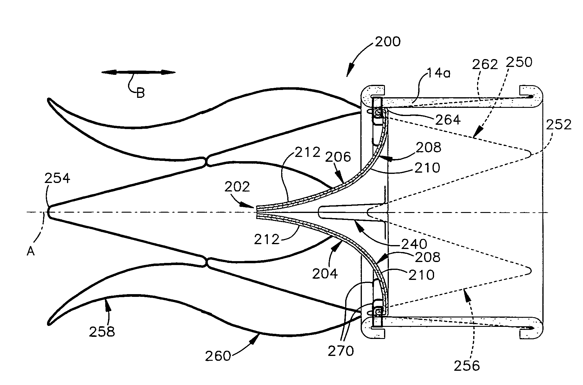
[0088]FIG. 6 is a longitudinal sectional view of an apparatus 10a constructed in accordance with the present invention. Structures of the embodiment shown in FIG. 6 that are similar to structures of FIGS. 1-3 have the same reference numbers with the suffix “a” added. The apparatus 10a is identical to apparatus 10 of FIGS. 1-3 with the exception that the layer of biological tissue 14a in the embodiment of FIG. 6 includes only a layer 18a of serous membrane.

[0089]The layer of biological tissue 14a is harvested to include only the layer 18a of serous membrane. The method for harvesting only a layer 18a of serous membrane is known in the art

[0090]The assembly of apparatus 10a is identical to the assembly of apparatus 10 that is illustrated in FIGS. 4a-4f. When trimmed into the desired shape, the layer of biological tissue 14a includes first and second side surfaces 42a and 44a, respectively, and first and second axial ends 58a and 60a, respectively.

[0091]The assembled apparatus includes...

third embodiment

[0093]FIG. 7 is a longitudinal sectional view of an apparatus 10b constructed in accordance with the present invention. Structures of the embodiment shown in FIG. 7 that are similar to structures of FIGS. 1-3 have the same reference numbers with the suffix “b” added.

[0094]The apparatus 10b illustrated in FIG. 7 includes a layer of biological tissue 14b and an expandable support member 16b. The layer of biological tissue 14b includes a serous membrane lining 18b and associated fascia lining 20b. The expandable support member 16b has a structure similar to that illustrated in FIG. 1. The layer of biological tissue 14b forms the innermost component of the apparatus 10b.

[0095]The layer is biological tissue 14b is formed into a tubular portion by abutting first and second side surfaces 42b and 44b of the biological tissue 14b at a seam 46b. Preferably, the first and second side surfaces 42b and 44b are sutured together at the seam 46b and biological glue (not shown) is applied to an out...

fourth embodiment

[0098]FIG. 8 is a longitudinal sectional view of an apparatus 10c constructed in accordance with the present invention. Structures of the embodiment shown in FIG. 8 that are similar to structures of FIG. 7 have the same reference numbers with the suffix “c” replacing the suffix “b”. The apparatus 10c is identical to apparatus 10b of FIG. 7 with the exception that the layer of biological tissue 14c in the embodiment of FIG. 8 includes only a layer 18c of serous membrane.

[0099]The assembly of apparatus 10c is identical to the assembly of apparatus 10b. When trimmed into the desired shape, the layer of biological tissue 14c includes first and second side surfaces 42c and 44c, respectively, and first and second axial ends 58c and 60c, respectively.

[0100]The assembled apparatus includes a seam 46c that is formed from abutting the first and second side surfaces 42c and 44c. The inner surface 48c of the assembled apparatus 10c is defined by the inner surface 50c of the layer 18c of serous ...


PUM

PropertyMeasurementUnit
shapeaaaaaaaaaa
flexibleaaaaaaaaaa
elasticityaaaaaaaaaa

Abstract

A prosthetic valve for replacing a cardiac valve includes an expandable support member and at least two valve leaflets made of a first layer of biological material selected from peritoneal tissue, pleural tissue or pericardial tissue. A second layer of biological material is attached to the support member. The second layer is also made from peritoneal tissue, pleural tissue or pericardial tissue. The second layer includes a radially inwardly facing surface that defines a conduit for directing blood flow. The valve leaflets extend across the conduit to permit unidirectional flow of blood through the conduit. Methods for making and implanting the prosthetic valve are also provided.

Description

RELATED APPLICATIONS[0001]This application is a continuation-in-part application U.S. patent application Ser. No. 10 / 409,884, filed Apr. 9, 2003 now U.S. Pat. No. 7,137,947, which is a divisional application of Ser. No. 09 / 908,764 now U.S. Pat. No. 6,579,307, filed Jul. 19, 2001 and issued Jun. 17, 2003, both of which are assigned to the assignee of the present invention and are incorporated herein by reference.TECHNICAL FIELD[0002]The present invention relates to a prosthetic cardiac valve and methods for making and implanting the prosthetic valve.BACKGROUND OF THE INVENTION[0003]Surgical procedures in which a cardiovascular prosthesis is implanted into a patient's blood vessel are common in treating many vascular disorders. For example, one common type of cardiovascular prosthesis is an endovascular prosthesis that is used to strengthen a blood vessel wall in the location of an aneurysm, or to open an occlusion in a blood vessel.[0004]A typical endovascular prosthesis includes a f...

Claims


Application Information

Patent Timeline
Patent Type & Authority Patents(United States)
IPC IPC(8): A61F2/06A61F2/24A61L27/36A61L31/00
CPCA61F2/2415A61F2/2418A61F2/2475A61L27/3604A61L27/3641A61L27/3645A61L31/005A61L27/507Y10S623/915A61F2220/0008A61F2220/0016A61F2230/0054A61F2230/008
Inventor SARAC, TIMUR PAULSMEDIRA, NICHOLAS G.
Owner THE CLEVELAND CLINIC FOUND
Why Eureka
Try Eureka