Imaging methods and apparatus having extended dynamic range

a dynamic range, imager technology, applied in the field of imaging systems, can solve problems such as loss of details associated with images

Active Publication Date: 2008-05-27
SRI INTERNATIONAL
View PDF10 Cites 18 Cited by
  • Summary
  • Abstract
  • Description
  • Claims
  • Application Information

AI Technical Summary

Problems solved by technology

If the photonic charge incident on the surface of the imaging device is outside of this range, detail associated with an image is lost.

Method used


Image

  • Imaging methods and apparatus having extended dynamic range
  • Imaging methods and apparatus having extended dynamic range
  • Imaging methods and apparatus having extended dynamic range

Examples


Embodiment Construction

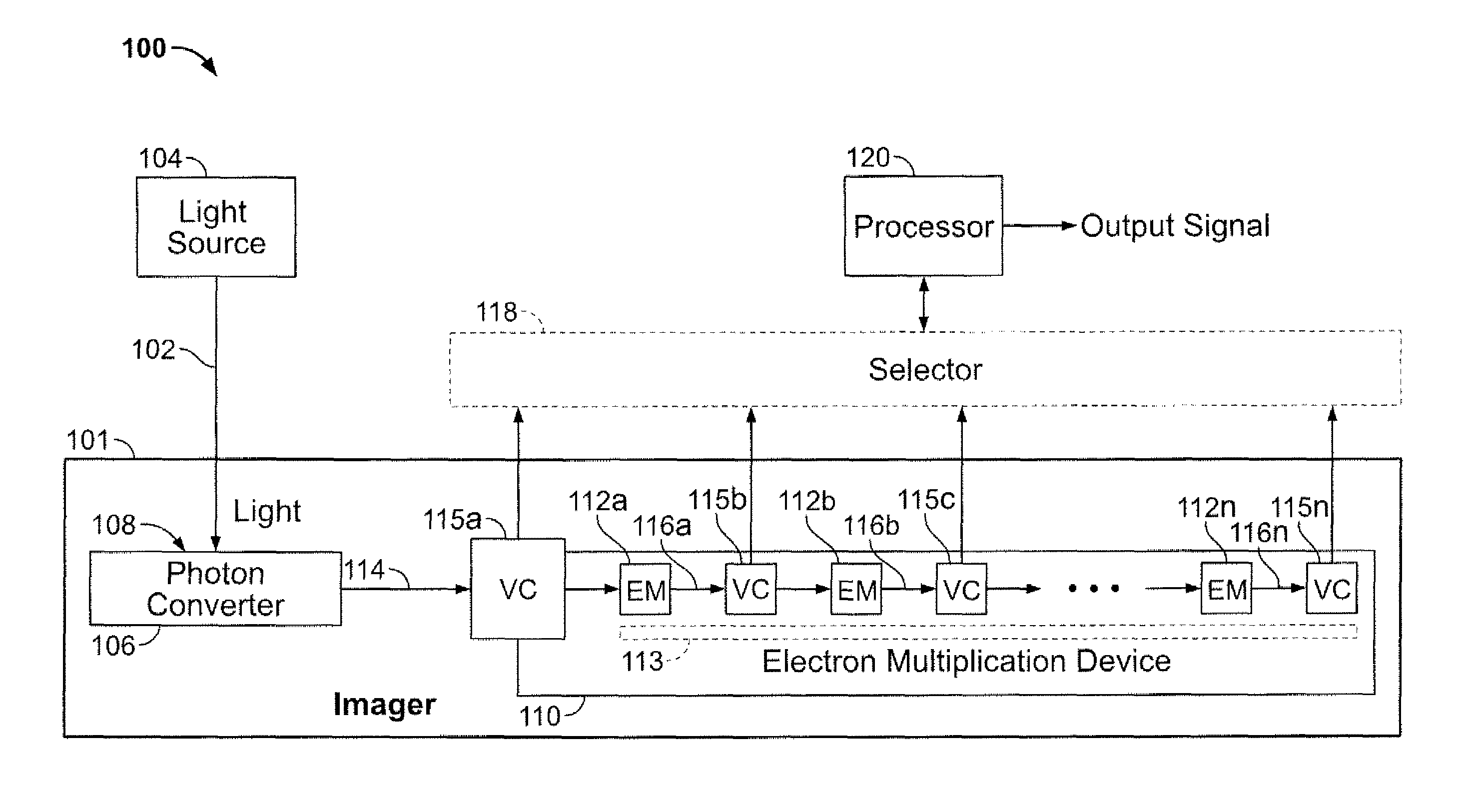
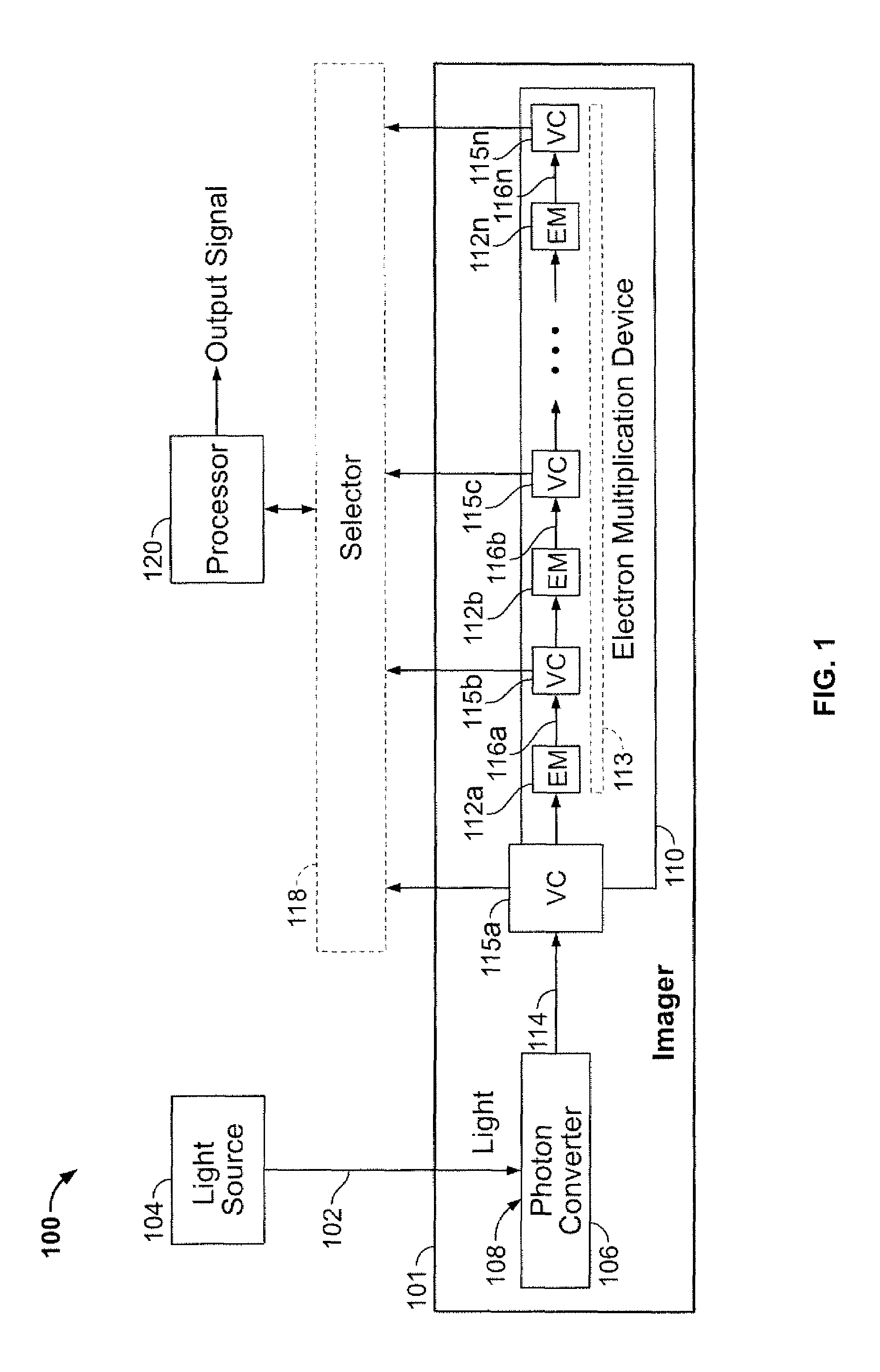
[0012]FIG. 1 depicts exemplary imaging apparatus 100 for imaging light 102 from a light source 104. The light source 104 may be a scene from a surveillance camera, an image from a telescope, or an image of a scanned document. Other suitable light sources 104 that produce light 102 which can be imaged by the exemplary imaging apparatus 100 will be understood by one of skill in the art from the description herein.

[0013]A photon converter 106 of an imager 101 collects the light 102 and converts the collected light 102 into electrical charge. In an exemplary embodiment, the photon converter 106 is a charge coupled device (CCD) that converts the photons of the light 102 that impinge upon a surface 108 of the photon converter 106 into electrical charge. The photon converter 106 may be a single pixel, line array, area array, starring array, or a time delay and integrate (TDI) array. An exemplary starring array is described in U.S. Pat. No. 3,953,733 to Levine entitled METHOD OF OPERATING I...


PUM

PropertyMeasurementUnit
electrical chargeaaaaaaaaaa
voltageaaaaaaaaaa
signal-to-noise ratioaaaaaaaaaa

Abstract

Methods and apparatus for imaging light are disclosed. Light is imaged by collecting light, converting the collected light into a electrical charge signal, multiplying the electrical charge signal to produce multiple electrical charge signals with associated levels of gain, converting the electrical charge signals to voltage signals, and developing an output signal from one or more of the voltage signals that represents the collected light. The electrical charge signal may be multiplied using an electron multiplication device associated with multiple taps to produce the electrical charge signal with different levels of gain.

Description

CROSS-REFERENCE TO RELATED APPLICATION[0001]This application claims the benefit of U.S. Provisional Application No. 60 / 591,289, filed Jul. 27, 2004, the contents of which are incorporated herein by reference.FIELD OF THE INVENTION[0002]The present invention relates to imaging systems and, more particularly, to extending the dynamic range of imagers.BACKGROUND OF THE INVENTION[0003]Imagers collect photonic charge from an image using imaging devices such as charge coupled device (CCD) arrays. A typical CCD array incorporates photosensitive devices arranged in rows and columns to collect photonic charge. The photosensitive devices convert collected photonic charge into electrical charge. The electrical charge is then accumulated across multiple photosensitive devices, e.g., by row or column, to capture the image.[0004]Imaging devices are able to handle a range of photonic charge that depends on their design. If the photonic charge incident on the surface of the imaging device is outsid...

Claims


Application Information

Patent Timeline
Patent Type & Authority Patents(United States)
IPC IPC(8): H01J40/14H03K23/46H04N3/14H04N5/355H04N5/357H04N5/372H04N5/378
CPCH04N5/238H04N23/75
Inventor TOWER, JOHN ROBERTSONLEVINE, PETER ALAN
Owner SRI INTERNATIONAL
Why Eureka
Try Eureka