Acoustic wave resonator with integrated temperature control for oscillator purposes

a technology of oscillator and temperature control, applied in piezoelectric/electrostrictive/magnetostrictive devices, piezoelectric/electrostriction/magnetostriction machines, impedence networks, etc., can solve the problem of not being able to support several telecommunications systems without increasing the size of a mobile phone, and unable to withstand high power levels, etc. problem, to achieve the effect of improving frequency accuracy

Inactive Publication Date: 2008-05-27
NOKIA CORP
View PDF38 Cites 17 Cited by
  • Summary
  • Abstract
  • Description
  • Claims
  • Application Information

AI Technical Summary

Benefits of technology

[0013]It is an object of the present invention to provide a resonator structure with improved frequency accuracy.
[0025]Accordingly, at least one integrated heating element is provided on the substrate of the resonator structure, so that the heating element is located very close to the resonator structure itself. The temperature control is thus quite accurate and variation of heating elements and resonator can be individually calibrated for every resonator sample.
[0026]The controllable heating element may be configured to be used as a temperature sensing element for sensing local temperature of the resonator structure. As an alternative or additional measure, at least one dedicated temperature sensing element may be integrated on the substrate and configured to sense local temperature of the resonator structure. This provides the advantage that the dependency or characteristic between frequency and temperature of the resonator structure can be measured continuously and the stored characteristic can be adapted at a predetermined timing.

Problems solved by technology

The development of mobile telecommunications continues towards ever smaller and increasingly complicated handheld units or mobile phones.
This approach has been adequate for single standard phones, but does not allow support of several telecommunications systems without increasing the size of a mobile phone.
A SAW resonator has the advantage of having a very small size, but unfortunately cannot withstand high power levels.
BAW resonators are not yet in widespread use, partly due to the reason that feasible ways of combining such resonators with other circuitry have not been presented.

Method used


Image

  • Acoustic wave resonator with integrated temperature control for oscillator purposes
  • Acoustic wave resonator with integrated temperature control for oscillator purposes
  • Acoustic wave resonator with integrated temperature control for oscillator purposes

Examples


Embodiment Construction

[0041]In the following, embodiments of the present invention will be described in more detail based on specific BAW and SAW resonator structures.

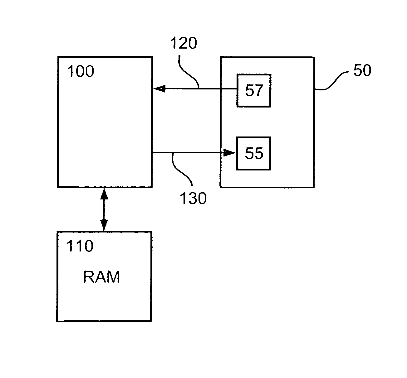
[0042]There are a two implementation examples where the embodiments described hereinafter can be used. Firstly in a reference oscillator, to replace a conventional crystal, and secondly in local oscillator circuits for transmission / reception (TX / RX) frequency generation. Both cases require an accurate and well-defined temperature behavior. The pure resonator is useful directly for oscillator purposes, so that the present invention enables more accurate oscillator circuits.

[0043]In particular, the below embodiments could be used in a crystal-less oscillator used as a reference oscillator circuit of an RF transceiver as described for example in WO2004 / 045101A1 and which can be used in mobile phones or mobile terminals for wireless networks

[0044]The preferred first embodiment relates to a BAW structure, particularly a Solidly Mounted Resonator...


PUM


Abstract

The present invention relates to a resonator structure, temperature compensation method and temperature control apparatus for controlling local temperature of a resonator structure. At least one heating element (55) is integrated on a substrate of the resonator structure, and a temperature control signal generated based on a stored temperature characteristic is applied to the at least one integrated heating element (55). Thereby, the at least one heating element (55) and an optional integrated sensing element can be provided very close to the resonator. It is thus possible to control or calibrate variations of sensing elements, heating elements and resonator out from every sample.

Description

FIELD OF THE INVENTION[0001]The present invention relates to a resonator structure integrated on a substrate. In particular the present invention relates to film bulk acoustic wave resonator (FBAR) or surface acoustic wave (SAW) resonator structures.BACKGROUND OF THE INVENTION[0002]The development of mobile telecommunications continues towards ever smaller and increasingly complicated handheld units or mobile phones. The development has recently led to new requirements for handheld units, namely that the units should support several different standards and telecommunications systems. Supporting several different systems requires several sets of filters and other radio frequency (RF) components in the RF parts of the handheld units. Despite this complexity, the size of a handheld unit should not increase as a result of such a wide support.[0003]RF filters used in prior art mobile phones are usually discrete surface acoustic wave (SAW) or ceramic filters. This approach has been adequa...

Claims


Application Information

Patent Timeline
Patent Type & Authority Patents(United States)
IPC IPC(8): H01L41/08
CPCH03H9/02102H03H9/02834
Inventor VILANDER, ARI
Owner NOKIA CORP
Why Eureka
Try Eureka