Optical module for atomic oscillator and atomic oscillator

A technology of atomic oscillators and optical modules, applied in phonon exciters, instruments, lasers, etc., can solve the problems of frequency accuracy reduction, EIT signal broadening, etc.

Inactive Publication Date: 2013-07-17
SEIKO EPSON CORP
View PDF5 Cites 11 Cited by
  • Summary
  • Abstract
  • Description
  • Claims
  • Application Information

AI Technical Summary

Problems solved by technology

As a result, the line width (optical absorption width) of the obtained EIT signal tends to become wider, and the frequency accuracy decreases

Method used


Image

  • Optical module for atomic oscillator and atomic oscillator
  • Optical module for atomic oscillator and atomic oscillator
  • Optical module for atomic oscillator and atomic oscillator

Examples


no. 1 Embodiment approach

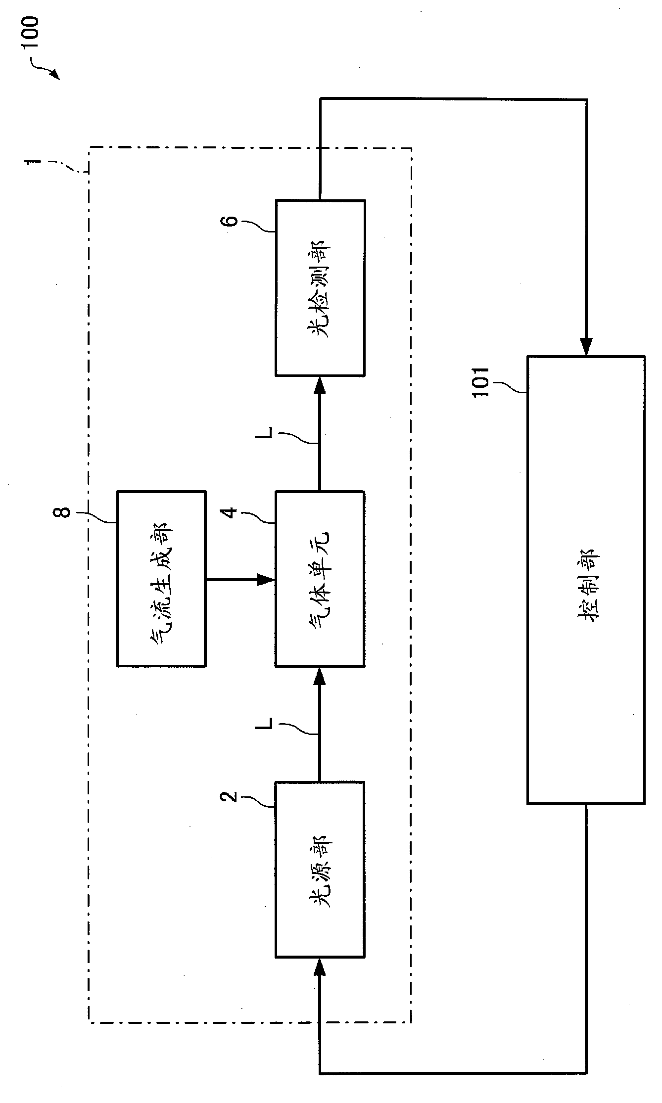
[0034] First, the atomic oscillator according to the first embodiment will be described with reference to the drawings. figure 1 It is a functional block diagram of the atomic oscillator 100 according to the first embodiment.

[0035] The atomic oscillator 100 is an oscillator utilizing the quantum interference effect (EIT phenomenon). The atomic oscillator 100 includes an optical module 1 and a control unit 101 .

[0036] The optical module 1 includes a light source unit 2 , a gas unit 4 , a light detection unit 6 , and an air flow generation unit 8 .

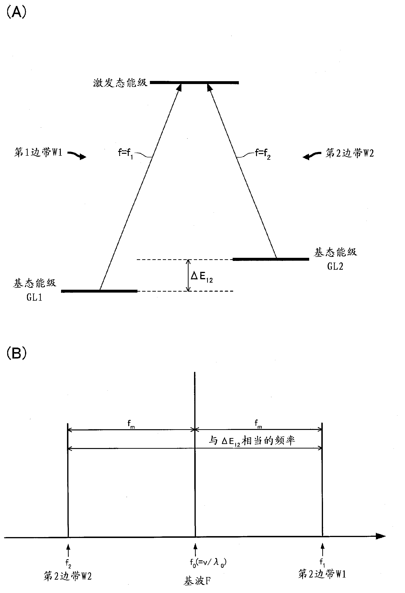
[0037] The light source unit 2 emits resonant light L having two different wavelengths. The resonant light L generated in the light source unit 2 contains 0 The upper sideband has frequency f 1 = f 0 + f m The first sideband W1; and relative to the center frequency f 0 The lower sideband has frequency f 2 = f 0 - f m The 2nd sideband W2 (refer to figure 2 ).

[0038] The resonance light L is irradiated to the gas ...

no. 2 Embodiment approach

[0082] Next, an atomic oscillator according to a second embodiment will be described with reference to the drawings. Figure 8 It is a perspective view schematically showing the optical module 201 of the atomic oscillator of the second embodiment. Figure 9 is a cross-sectional view schematically showing the optical module 201 . also, Figure 9 yes Figure 8 IX-IX line sectional view. Hereinafter, in the optical module 201 of the second embodiment, the same reference numerals are assigned to the same functional components as the components of the optical module 1 of the first embodiment, and detailed description thereof will be omitted.

[0083] In the optical module 201, such as Figure 8 as well as Figure 9 As shown, the air flow generating unit 108 includes a light emitting unit 210 and a light absorbing unit 220 that absorbs light emitted from the light emitting unit 210 .

[0084] The light emitting unit 210 can supply heat by irradiating light to the gas cell 4 . ...


PUM


Abstract

The invention provides an optical module for atomic oscillator and an atomic oscillator. An optical module for an atomic oscillator by using a quantum interference effect includes a light source part to emit resonant light having two different wavelengths, a gas cell in which an alkali metal atom gas is enclosed and to which the resonant light is irradiated, a light detection part to detect an intensity of the resonant light transmitted through the gas cell, and a gas-flow generation part to generate a flow of the alkali metal atom gas.

Description

technical field [0001] The present invention relates to an optical module for an atomic oscillator and an atomic oscillator. Background technique [0002] In recent years, atomic oscillators using CPT (Coherent Population Trapping), which is one of the quantum interference effects, have been proposed, and miniaturization and low power consumption of devices are expected. The atomic oscillator using CPT is an oscillation that utilizes the phenomenon (EIT phenomenon: Electromagnetically Induced Transparency: Electromagnetically Induced Transparency: Electromagnetically Induced Transparency: Electromagnetically Induced Transparency) that stops the absorption of coherent light when alkali metal atoms are irradiated with coherent light having two different wavelengths (frequency). device. [0003] In an atomic oscillator, an alkali metal atom such as rubidium (Rb) or cesium (Cs) is usually enclosed in a container (gas cell) made of silicon oxide or the like, and the EIT phenomen...

Claims


Application Information

Patent Timeline
Patent Type & Authority Applications(China)
IPC IPC(8): H03L7/26
CPCG01R33/44G04F5/145H03L7/26H01S1/06H01S5/0687G01R33/26G21K1/006G01C19/60H01S5/0427
Inventor 西田哲朗
Owner SEIKO EPSON CORP
Why Eureka
Try Eureka