Clock Circuit And Method For Recalibrating An Injection Oscillator Coupled To Kick-Start A Crystal Oscillator

a clock circuit and crystal oscillator technology, applied in the direction of oscillator generators, pulse automatic control, pulse technique, etc., can solve the problems of injection oscillators, long start-up time, and additional system design hurdles, and achieve high accuracy

Active Publication Date: 2020-03-26
SILICON LAB INC
View PDF3 Cites 10 Cited by
  • Summary
  • Abstract
  • Description
  • Claims
  • Application Information

AI Technical Summary

Benefits of technology

[0022]The decision circuitry may be coupled to supply a recalibration signal to the digital frequency calibration circuit to update the digital control signal supplied to the injection oscillator. In some embodiments, for example, the decision circuitry may supply a recalibration signal to the digital frequency calibration circuit in response to at least one of the following: a time duration since the injection frequency was last calibrated exceeds a first...

Problems solved by technology

The higher the Q-factor, the longer it takes for the oscillation signal generated by the oscillator to reach its final amplitude, resulting in a longer start-up time.
Waiting for a crystal oscillator to start up can be a significant source of power consumption in a low power radio design, and may create additional system design hurdles in applications where the radio needs to be on during a specific window to receive or transmit packets.
Unfortunately, injection oscillators commonly used to kick-start crystal oscillator circuits are unable to maintain a sufficiently accurate injection frequency to produce the desired result.
Although the modulation schemes shown in FIG. 2 (Prior Art) and FIG. 3 (Prior Art) improve start-up performance to some...

Method used


Image

  • Clock Circuit And Method For Recalibrating An Injection Oscillator Coupled To Kick-Start A Crystal Oscillator
  • Clock Circuit And Method For Recalibrating An Injection Oscillator Coupled To Kick-Start A Crystal Oscillator
  • Clock Circuit And Method For Recalibrating An Injection Oscillator Coupled To Kick-Start A Crystal Oscillator

Examples


Embodiment Construction

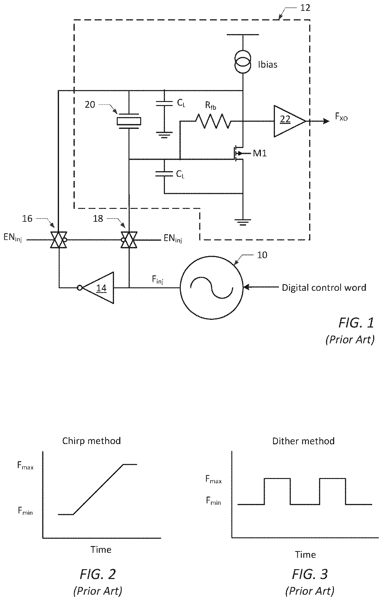
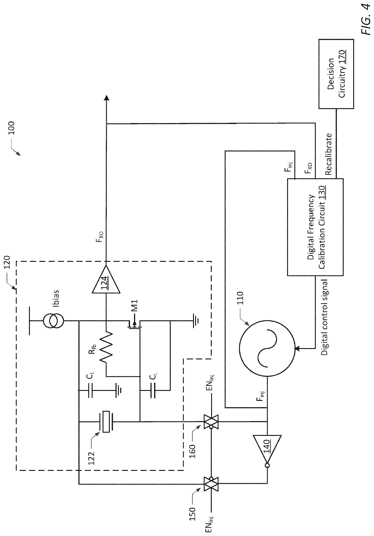
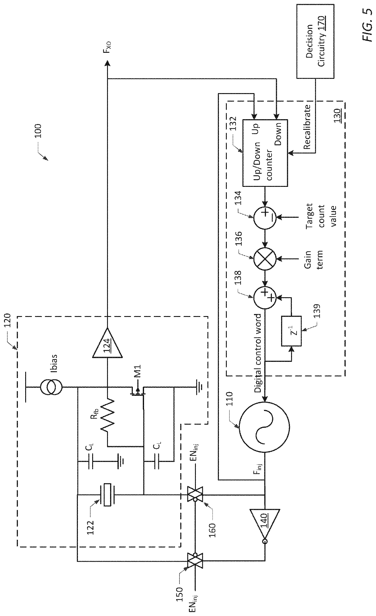
[0035]FIG. 4 provides a simplified circuit diagram of a clock circuit 100, according to one embodiment of the present disclosure. Similar to the clock circuit shown in FIG. 1 (Prior Art), clock circuit 100 includes an injection oscillator 110, which is coupled to supply an input oscillation signal at an injection frequency, Finj, to kick-start a crystal oscillator circuit 120, which is configured to provide an output oscillation signal at a resonant frequency, FXO. Injection oscillator 110 must have a fast startup time, usually achieved by having a low effective Q-factor. As such, injection oscillator 110 may be otherwise referred to herein as a fast-starting oscillator. Also, the injection oscillator 110 frequency must be able to be controlled by a digital control signal. Injection oscillator 110 may be implemented using any known type of oscillator including, but not limited to, ring oscillators or various forms of relaxation oscillators.

[0036]Like the clock circuit shown in FIG. ...


PUM


Abstract

Embodiments of clock circuits disclosed herein include a crystal oscillator circuit, an injection oscillator coupled to kick-start the crystal oscillator circuit and a digital frequency calibration circuit coupled to recalibrate the injection oscillator. The crystal oscillator circuit is configured to generate a clock signal at a resonant frequency. The injection oscillator is coupled to supply an oscillation signal at an injection frequency to the crystal oscillator circuit to reduce a start-up time of the crystal oscillator circuit. The digital frequency calibration circuit is coupled to receive the resonant frequency and the injection frequency as inputs, and configured to supply a digital control signal to the injection oscillator to set the injection frequency of the injection oscillator substantially equal to the resonant frequency of the crystal oscillator circuit. Methods are provided herein to recalibrate the injection frequency of an injection oscillator over time, temperature and/or supply voltage.

Description

BACKGROUND1. Field of the Disclosure[0001]This disclosure relates to clock circuits and, more particularly, to clock circuits and methods to recalibrate an injection oscillator coupled to kick-start a crystal oscillator.[0002]2. Description of the Relevant Art[0003]The following descriptions and examples are provided as background only and are intended to reveal information that is believed to be of possible relevance to the present disclosure. No admission is necessarily intended, or should be construed, that any of the following information constitutes prior art impacting the patentable character of the subject matter claimed herein.[0004]Radio frequency (RF) transceivers (as well as other electronic systems and circuits) often require a high precision and low noise reference clock source for normal operation. Such a clock source may be provided, in some cases, by a crystal oscillator circuit. In low power applications, it is common for an RF transceiver to spend much of its time ...

Claims


Application Information

Patent Timeline
IPC IPC(8): H03B5/06H03B5/36H03K21/38H03L3/00
CPCH03K21/38H03B2200/0094H03L3/00H03B5/366H03B5/06H03B5/26H03B5/362H03B2200/0074H03L7/08H03L7/10
Inventor POWELL, MATTHEWSARKAR, SUDIPTA
Owner SILICON LAB INC
Why Eureka
Try Eureka