
Noise reduction system, noise reduction method, recording medium, and electronic camera

a noise reduction and noise reduction technology, applied in the field of image processing technique, can solve the problems of image degrading resolution and image becoming a “blurred” image, and achieve the effect of preventing the degrading of resolution and eliminating the noise of image data

Active Publication Date: 2008-06-03
OLYMPUS CORP
View PDF19 Cites 32 Cited by
  • Summary
  • Abstract
  • Description
  • Claims
  • Application Information

AI Technical Summary

Benefits of technology

The present invention aims to remove noise from image data without degrading resolution. A noise reduction system is described that calculates representative values from the level values of pixels in a predetermined direction and selects one representative value based on a predetermined condition. The level value of an observed pixel is then replaced with the selected representative value to remove noise. This results in a cleaner image without degraded resolution.

Problems solved by technology

Therefore, there is a problem that the image obtained using that process is degraded in resolution, and, namely, the image becomes a “blurred” image.

Method used


Image

  • Noise reduction system, noise reduction method, recording medium, and electronic camera
  • Noise reduction system, noise reduction method, recording medium, and electronic camera
  • Noise reduction system, noise reduction method, recording medium, and electronic camera

Examples


Embodiment Construction

[0024]Hereinafter, preferred embodiments according to the present invention are explained with reference to the drawings.

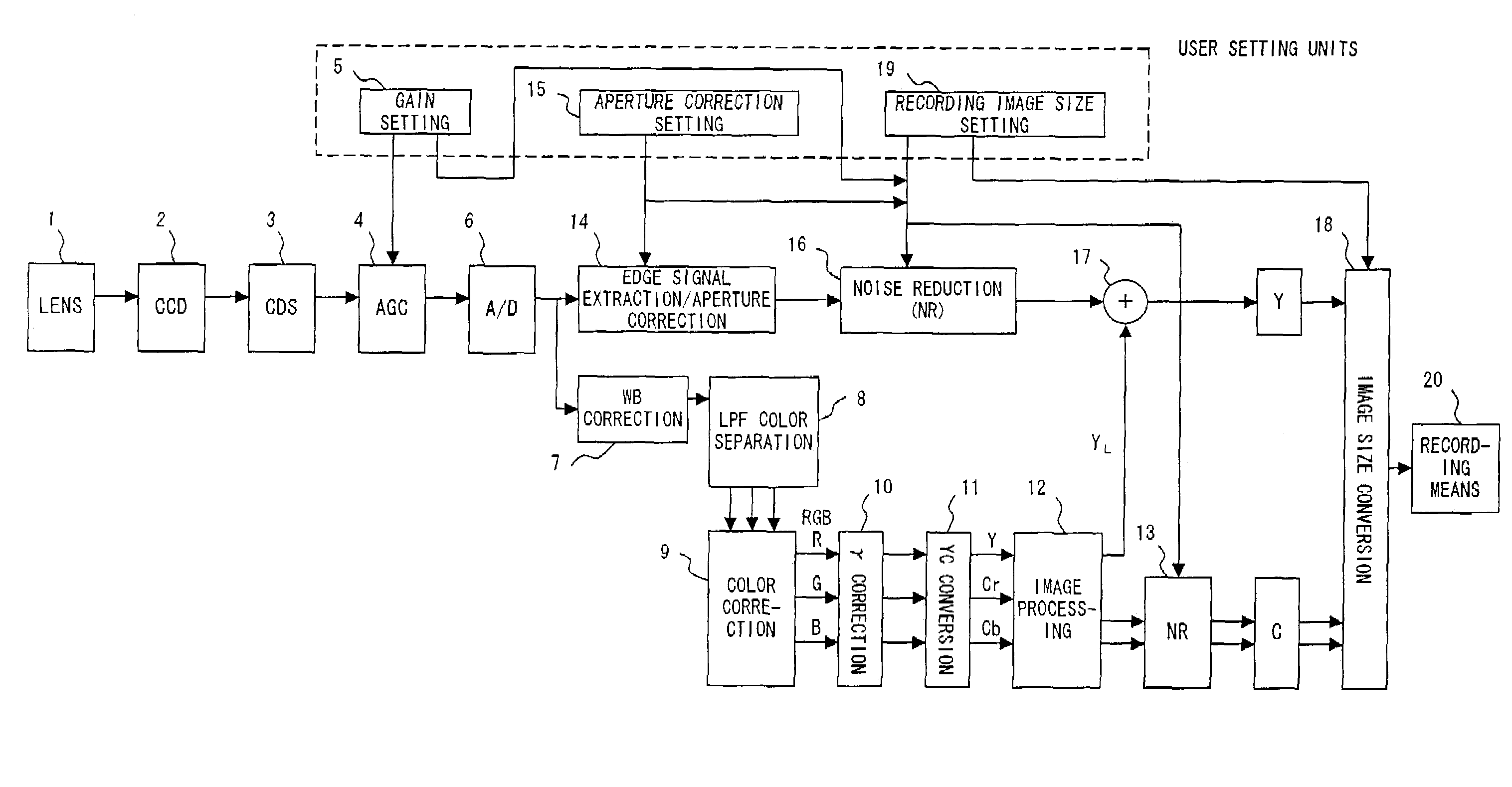
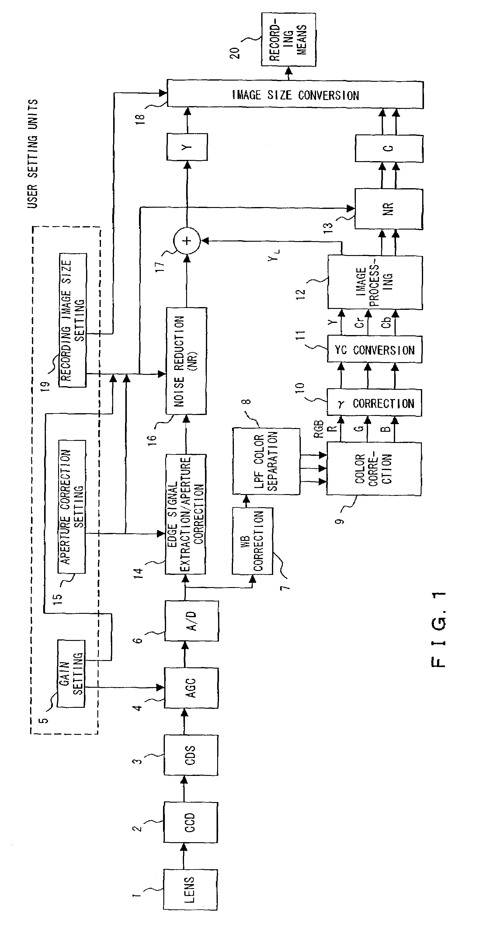
[0025]FIG. 1 is a block diagram exemplifying the configuration of an electronic camera according to a first preferred embodiment of the present invention.

[0026]As shown in this figure, this electronic camera comprises: a shooting (i.e. taking) lens 1; a CCD (Charge-Coupled Device) 2 opt-electrically converting an optical subject image formed by the shooting lens 1, and generating an electric signal corresponding to the subject image; a CDS (Correlated Double Sampling) circuit 3 extracting an image signal component from the output signal of the CCD 2; an AGC (Automatic Gain Control) circuit 4 adjusting the level of the output signal of the CDS circuit 3 to a predetermined gain value; a gain setting means 5 setting a gain value according to an instruction from a user; an A / D converter 6 converting an analog image signal output from the AGC circuit 4 to a digital ima...


PUM


Abstract

A noise reduction system comprises an inputting unit inputting image data, and a noise reduction unit performing a process for removing noise of the image data input by the inputting unit. The noise reduction unit includes a representative value calculating unit calculating a representative value from the level values of a plurality of pixels in a predetermined direction, which include an observed pixel of the input image data, a representative value selecting unit selecting one representative value according to a predetermined condition from among a plurality of representative values which are calculated by the representative value calculating unit and correspond to a plurality of directions, and a replacing unit replacing the level value of the observed pixel with the representative value selected by the representative value selecting unit.

Description

BACKGROUND OF THE INVENTION[0001]1. Field of the Invention[0002]The present invention relates to an image processing technique, and more particularly, to a technique for removing noise from an image that is represented by digital data.[0003]2. Description of the Related Art[0004]Conventionally, a smoothing filter is generally used in a process for removing noise of an image that is represented by digital data.[0005]For example, Japanese Patent Publication No. 2000-069291 discloses a technique for preventing an image from being degraded by changing the characteristic of an applied smoothing filter according to the characteristic of input image data.[0006]Additionally, for example, Japanese Patent No. 3165225 discloses a technique for removing extraneous noise by applying a noise removal filter (smoothing filter) only to a portion of a low luminance level, which is significantly influenced by extraneous noise applied to a luminance signal, in luminance to density conversion.[0007]Howe...

Claims


Application Information

Patent Timeline
Patent Type & Authority Patents(United States)
IPC IPC(8): H04N5/217G06K9/40H04N1/38H04N1/46H04N5/208G06T5/00H04N1/409H04N5/21H04N23/12H04N101/00
CPCH04N5/357H04N25/60
Inventor HIGUCHI, MASAYU
Owner OLYMPUS CORP
Learn More