High intrascene dynamic range NTSC and PAL imager

a dynamic range, high-intersect technology, applied in the field of improved semiconductor imaging devices, can solve the problems of slow response of the log portion of the circuit, fixed pattern noise, difficult control of the knee point in the linear-to-log transition,

Active Publication Date: 2008-06-03
APTINA IMAGING CORP
View PDF24 Cites 48 Cited by
  • Summary
  • Abstract
  • Description
  • Claims
  • Application Information

AI Technical Summary

Problems solved by technology

First, the knee point in linear-to-log transition is difficult to control leading to fixed pattern noise in the output image.
Second, under low light the log portion of the circuit is slow to respond leading to lag.
Third, a logarithmic representation of the signal in the voltage domain (or charge domain) means that small variations in signal due to fixed pattern noise leads to large variations in represented signal.
Conventional implementations which vary integration time during frame capture have require additional logic and

Method used


Image

  • High intrascene dynamic range NTSC and PAL imager
  • High intrascene dynamic range NTSC and PAL imager
  • High intrascene dynamic range NTSC and PAL imager

Examples


Embodiment Construction

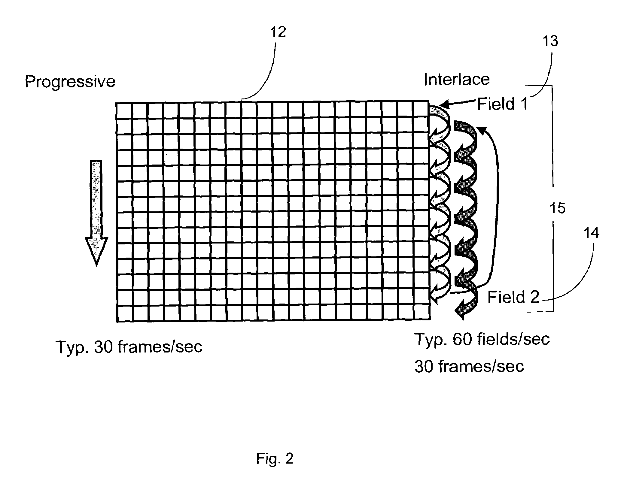
[0035]Conventional interlaced NTSC or PAL image sensors perform imaging in two field captures at two time periods. Performing NTSC or PAL compatible image capture using progressive scan style with dual sampling requires another approach. For example, referring to FIG. 3, samples with different integration time can be taken from two adjacent odd and even rows to produce each field of an NTSC and PAL image sensor so that high intrascene dynamic range is achieved with minimized circuitry. A fusion algorithm can then be used to produce progressive style output using image signals from adjacent rows of pixels where the pixels of odd and even rows have different integration times.

[0036]Referring to FIG. 3, integration can be performed within a pixel array 12 where odd rows (e.g., 16, 18, 20) of pixels and even rows (e.g., 17, 19, 21) of pixels have different integration periods. In an exemplary embodiment, odd row pixels have a longer integration period, Tlong, which commences first to pr...


PUM


Abstract

The invention provides a new method and apparatus for NTSC and PAL image sensors which employs fusion of adjacent row pixel charge samples to generate image data for a row. A variety of fusion schemes are possible for fusing the pixel signals from the adjacent rows. The rows of pixels are scanned so that each scan takes an odd row signal sample and, in some cases, an adjacent even row signal sample when specified conditions are met. One sampled row of the two adjacent rows integrate an image with a first integration period while the other adjacent row integrates an image with a second integration period.

Description

FIELD OF THE INVENTION[0001]The present invention relates generally to improved semiconductor imaging devices, and in particular to a CMOS imaging device having a high intrascene dynamic range.BACKGROUND OF THE INVENTION[0002]An important performance characteristic of imaging devices is dynamic range. A large dynamic range is desirable in applications for sensing low light signals and capturing images with large variations in illuminance or brightness.[0003]In particular, the dynamic range of an image sensor can be defined as the ratio of the minimum illuminance the sensor detects under saturation to the illuminance the sensor detects at signal-to-noise ratio (SNR) equal to 1. The dynamic range of a scene can also be expressed as the ratio of its highest illumination level to its lowest illumination level.[0004]Intrascene dynamic range refers to the range of incident signal that can be accommodated by a sensor in a single frame of imager data. Examples of scenes that generate high d...

Claims


Application Information

Patent Timeline
IPC IPC(8): H04N5/335H04N5/235H04N5/345H04N5/353H04N5/355H04N5/374H04N5/378
CPCH04N3/155H04N5/235H04N5/2355H04N23/70H04N23/741H04N25/583H04N25/616H04N25/75
Inventor CHO, KWANG-BOSUBBOTIN, IGORKAPLINSKY, MICHAELBARNA, SANDOR L.SLAYTON, GARY E.
Owner APTINA IMAGING CORP
Why Eureka
Try Eureka