Method and apparatus for guiding placement of vehicle service fixtures

a technology for vehicle service fixtures and positioning methods, applied in the direction of mechanical measuring arrangements, instruments, image enhancement, etc., can solve the problems of miscalculation of the rate of closure between the two, and achieve the effect of convenient placement of vehicle service apparatus, convenient positioning and convenient placement of collision avoidance system alignment fixtures

Active Publication Date: 2008-06-03
HUNTER ENG
View PDF29 Cites 59 Cited by
  • Summary
  • Abstract
  • Description
  • Claims
  • Application Information

AI Technical Summary

Benefits of technology

[0013]In an alternate embodiment, a machine vision vehicle wheel alignment system is configured to observe one or more optical targets mounted to a vehicle service apparatus. The vehicle wheel alignment system is configured to utilize data from images of the optical targets on the vehicle service apparatus, in conjunction with images of optical targets mounted to the vehicle wheels, to facilitate placement of the vehicle service apparatus relative to the vehicle.

Problems solved by technology

Any misalignment between the transmission vector and the direction of vehicle travel may result in misidentification of approaching objects, a miscalculation of the distances between the vehicle and the object, and accordingly, a miscalculation of the rate of closure between the two.

Method used


Image

  • Method and apparatus for guiding placement of vehicle service fixtures
  • Method and apparatus for guiding placement of vehicle service fixtures
  • Method and apparatus for guiding placement of vehicle service fixtures

Examples


Embodiment Construction

[0028]The following detailed description illustrates the invention by way of example and not by way of limitation. The description clearly enables one skilled in the art to make and use the invention, describes several embodiments, adaptations, variations, alternatives, and uses of the invention, including what is presently believed to be the best mode of carrying out the invention.

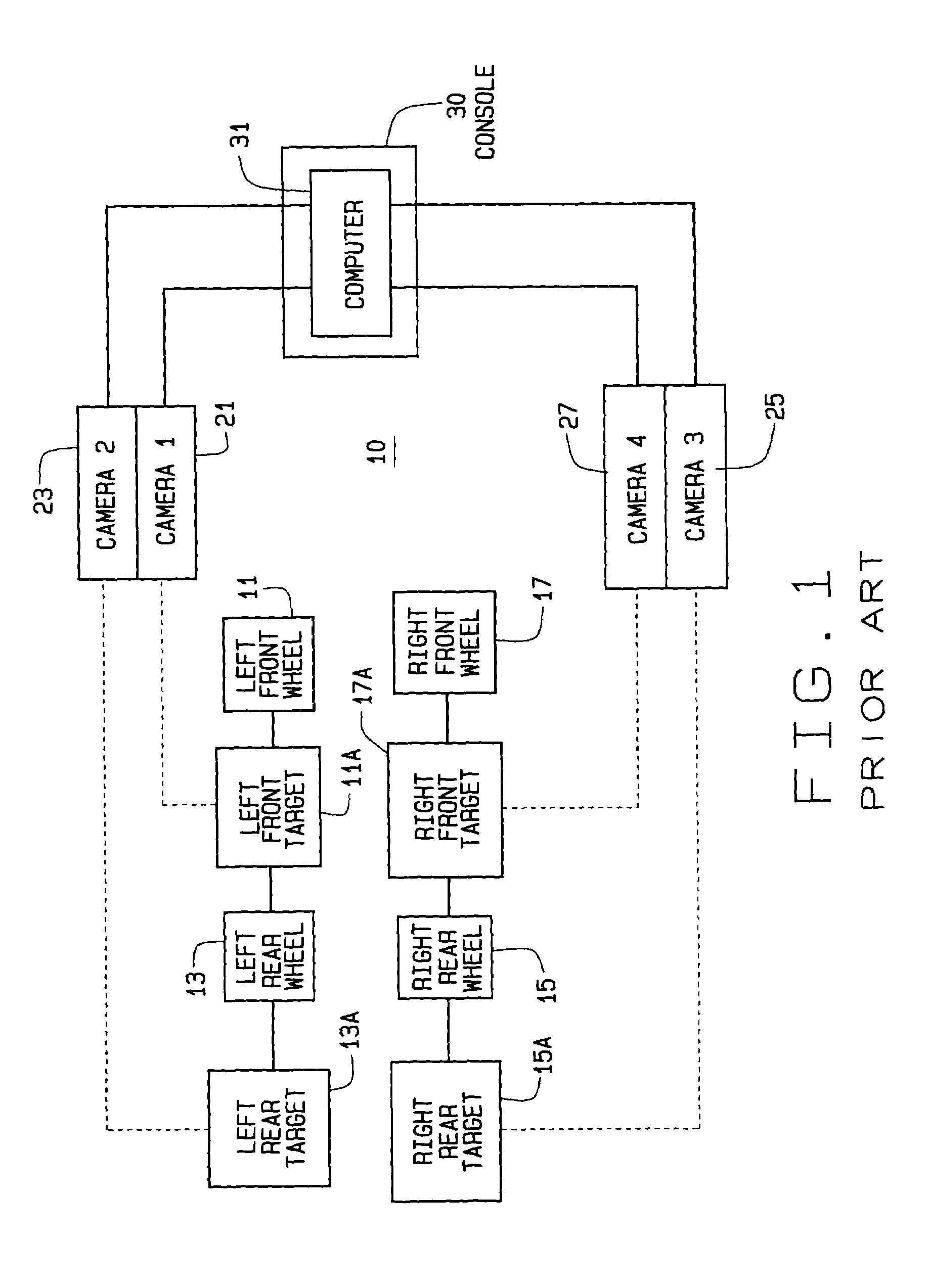
[0029]Turning to FIG. 1, the basic components of a conventional machine vision vehicle wheel alignment system, such as the Series 811 Aligner with the DSP600 sensors from Hunter Engineering Co. of Bridgeton, Mo. are shown generally at 10. The system 10 is configured to determine the position and orientation of vehicle wheels 11, 13, 15, and 17, and the axis about which they roll. Each vehicle wheel has associated therewith one or more optical targets 11A, 13A, 15A, and 17A. Optionally, additional optical targets may be associated other components of the vehicle, with a lift rack, or other support structur...


PUM

PropertyMeasurementUnit
frequencyaaaaaaaaaa
field of viewaaaaaaaaaa
alignment angleaaaaaaaaaa

Abstract

A machine vision system is configured to facilitate placement of a vehicle service apparatus relative to an associated vehicle. The machine vision system is configured to utilize images of optical targets received from one or more cameras to guide the placement of the vehicle service apparatus relative to the associated vehicle.

Description

CROSS-REFERENCE TO RELATED APPLICATIONS[0001]Not Applicable.STATEMENT REGARDING FEDERALLY SPONSORED RESEARCH[0002]Not Applicable.BACKGROUND OF THE INVENTION[0003]The present invention relates to the alignment of vehicle components relative to one or more features of a vehicle, and in particular, to methods and apparatus for adjusting the alignment of vehicle collision avoidance systems with the travel direction of the vehicle using machine vision components.[0004]Machine vision vehicle wheel alignment systems have been in use by the vehicle service industry for several years. A typical machine vision vehicle wheel alignment system, such as the Series 811 wheel alignment system, configured with the DSP600 sensors manufactured by Hunter Engineering Co. of Bridgeton, Mo. consists of a console unit, cameras, and optical targets. The console unit contains a computer configured with image processing and vehicle wheel alignment software applications, and incorporates various operator inter...

Claims


Application Information

Patent Timeline
Patent Type & Authority Patents(United States)
IPC IPC(8): G06K9/00G01B11/26G01B11/275G01C1/00G01S5/16G06T7/00
CPCG01B11/2755G06T7/004G01S5/16G01B2210/143Y10T29/53922G06T2207/30248G06T7/70
Inventor DORRANC, DANIEL R.STREGE, TIMOTHY A.BURNS, JR., LEIGH R.SHYLANSKI, MARK S.GOLAB, THOMAS J.
Owner HUNTER ENG
Why Eureka
Try Eureka