Optical fiber cable with system and method for mid-span access

a technology of optical fiber cable and mid-span access, applied in the direction of optics, fibre mechanical structure, instruments, etc., can solve the problems of inaccessible lower (inner) layers of loose tube cable, difficulty in mid-span access, and maintain significant drawbacks of current arrangement of such cables, etc., to achieve stable and robust stranding and high fiber count

Inactive Publication Date: 2008-06-03
NEXANS
View PDF3 Cites 38 Cited by
  • Summary
  • Abstract
  • Description
  • Claims
  • Application Information

AI Technical Summary

Benefits of technology

[0009]It is an object of the present invention to overcome the drawbacks associated with the prior art and to provide a high fiber count optical fiber cable that has both a stable and robust stranding, while simultaneously allowing for mid-span access of the individual fibers contained therein.
[0010]To this end the present invention is directed to an optical fiber cable that has a plurality of loose tubes, each of which contain at least one optical fiber. The loose tubes are constructed of a polymer having a low Young's constant modulus, such as a modulus resulting in a tensile strength substantially in the range of 2,500-2,800 PSI. The tubes are arranged in at least two layers, each of which are rotated in the same uni-helical direction, and where each of the at least two layers are arranged having substantially the same lay length. A jacket encases the loose tubes, such that a user, desiring access to any one of the optical fibers in one of the loose tubes, may open the jacket, untwist the at least two layers, access a desired loose tube and accompanying fiber contained therein and perform a desired splicing action.

Problems solved by technology

However, the current arrangement for such cables maintains significant drawbacks.
But, because of the general high fiber count construction, mid-span access proves to be difficult.
For example, the lower (inner) layers of the loose tube cables are typically inaccessible due to the stranding of the internal elements.
However, as noted above, such a helical stranding makes it difficult and at times impossible to achieve mid-span access of many of the fibers within the lose tubes inside the cable.
For example, with high fiber count optical fiber cables having multiple layers of loose tube optical fiber cables therein, mid-span access to fiber requires an un-twisting of the stranded cable, which is unworkable when there are multiple layers of loose tubes, each of different lay length and direction.
Additionally, the problem of un-twisting is exacerbated because the loose tubes employ plastics having a high Young's modulus which are particularly stiff.
However, S-Z designs are less robust stranding designs that tend to unravel or un-rotate over time as a result of temperature expansion, and by excessive handling of the cable during installation / relocation.
Use of S-Z may incorporate binders to hold the S-Z rotation, but such binders add yet another barrier to mid-span access of a fiber, add cost weight and additional stranding steps, and also results in undesirable crushing stresses on the fibers inside the tubes.
Another related drawback associated with the prior art in high fiber count optical fiber cables is that prior art cables typically use relatively high Young's modulus plastics for the loose tube construction.
However, in addition to being difficult to unwind for mid-span access due to their inherent stiffness, the use of such high modulus plastics exhibit higher temperature contraction reactions requiring, the tighter lay lengths in response.
However, such designs, in addition to making it more difficult to achieve mid-span access in helical stranded cables because of the tighter winding that needs to be unwound, such high modulus plastics impart some inherent fiber bend stresses which is locked in during manufacture by the twisting of the tubes, and may be augmented by the use of water blocking gels that assist in locking in this strain.
Such strain increases attenuation in the fibers and further hampers efforts for mid-span access.

Method used


Image

  • Optical fiber cable with system and method for mid-span access
  • Optical fiber cable with system and method for mid-span access
  • Optical fiber cable with system and method for mid-span access

Examples


Embodiment Construction

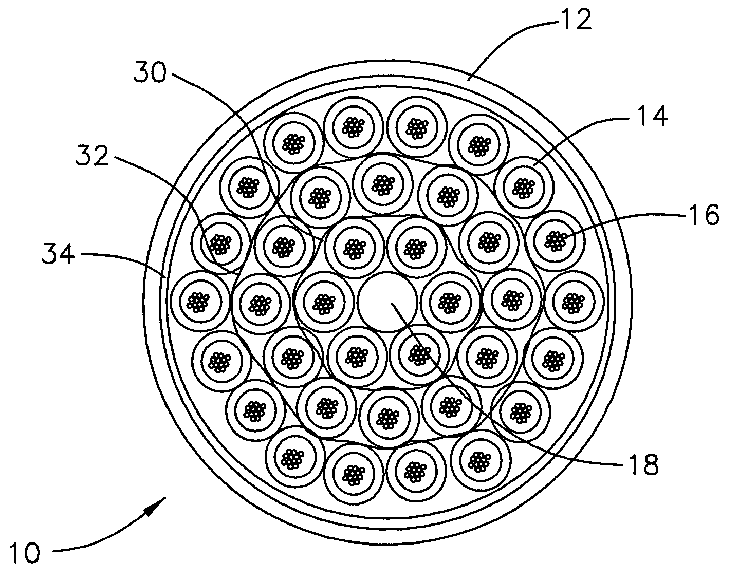
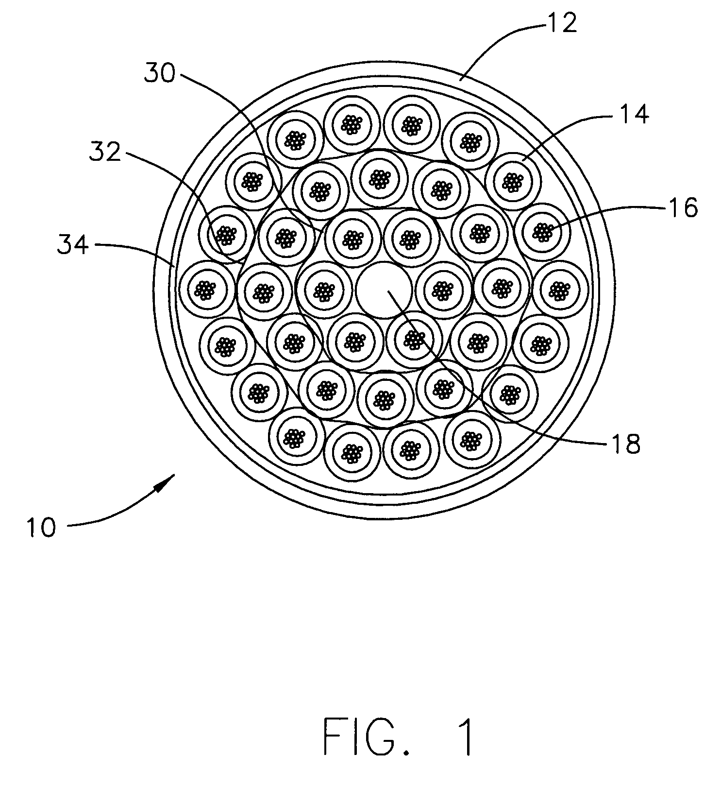
[0018]In one embodiment of the present invention, as illustrated in FIG. 1, a high fiber count optical fiber cable 10 is shown, having an outer jacket 12 and a number of loose tubes 14, each of which having a number of optical fibers 16 therein. A central strength member 18 is disposed centrally for added pulling and bending strength to cable 10.

[0019]Outer jacket 12 and loose tubes 14 are typically extruded polymers made from PVC compounds that exhibit Riser and Plenum rated fire resistance. A more detailed discussion of the composition of the polymers follows below. Optical fibers 16 may either be typical UV coated optical fibers (having a 250 micron diameter) or may be tight buffer (polymer coated) optical fibers (having a 900 micron diameter). For the purpose of illustration fibers 16 are discussed below as basic UV coated optical fibers 16.

[0020]Regarding the construction of loose tubes 14, each tube 14 is preferably an extruded polymer encasing twelve UV coated optical fibers ...


PUM


Abstract

An optical fiber cable includes a plurality of loose tubes, each of which contain at least one optical fiber therein. The loose tubes are constructed of a polymer with the tubes arranged in at least two layers, each of which are rotated in the same uni-helical direction and are ranged having substantially the same lay length. A jacket encases the loose tubes, where any one of the optical fibers in one of the loose tubes is accessible when the jacket is opened and the at least two layers are untwisted.

Description

FIELD OF THE INVENTION[0001]The present invention relates to the field of optical fiber cables. More particularly, the present invention relates to the field of high fiber count optical fiber cables.BACKGROUND OF THE INVENTION[0002]High fiber count cables are employed for installations that require a large number of fiber optic connections such as data centers or other computer / data transfer intensive applications. In order to address this need, high fiber count optical fiber cables are produced having increased fiber counts, typically in the range of 216 through 432 fibers.[0003]A typical high fiber count cable design includes an outer cable jacket, within which are multiple loose tube fiber cables arranged in layers around a central strength member. For example, a typical outer cable jacket may include eighteen loose tubes (one six tube layer and one twelve tube layer) to thirty six loose tubes (with an additional eighteen tube layer) therein. Within each loose tube fiber cable, a...

Claims


Application Information

Patent Timeline
Patent Type & Authority Patents(United States)
IPC IPC(8): G02B6/44
CPCG02B6/441G02B6/4495G02B6/4431
Inventor KELLER, DAVID
Owner NEXANS
Why Eureka
Try Eureka