This helps you quickly interpret patents by identifying the three key elements:
Problems solved by technology
Method used
Benefits of technology
[0013]In accordance with a first aspect of the invention, there is provided a pinless composite masonry block having a high unit mass per front surface square foot. The block comprises a front surface, a back surface, first and second sides, as well as a top surface and a bottom surface. The block sidewalls each may comprise an opening or inset extending from the
Problems solved by technology
However, when reliance on natural mechanisms is not possible or practical, man often resorts to the use of artificial mechanisms such as retaining walls.
Such definition is often not possible through use of a composite masonry block which results in a setback wall.
For example, a wall which sets back by its very nature will cross a property line and may also preclude maximization of usable land in the upper or subjacent property.
Besides being complex, anchoring mechanisms such as pin systems often rely on only one strand or section of support tether which, if broken, may completely compromise the structural integrity of the wall.
Reliance on such complex fixtures often discourages the use of retaining wall systems by the everyday homeowner.
Commercial landscapers may also avoid complex retaining wall systems as the time and expense involved in constructing t
Method used
Image
Click on the blue label to locate the original text in one second.
Reading with bidirectional positioning of images and text.
Examples
Example
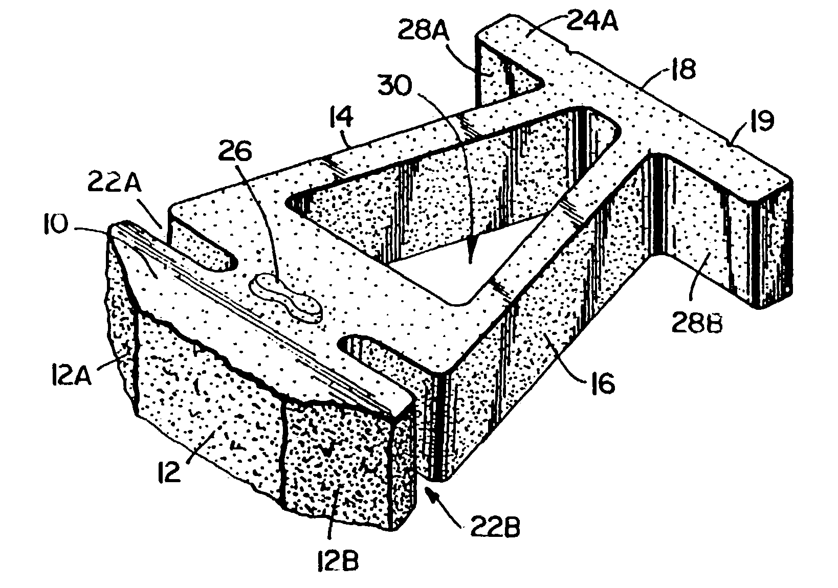
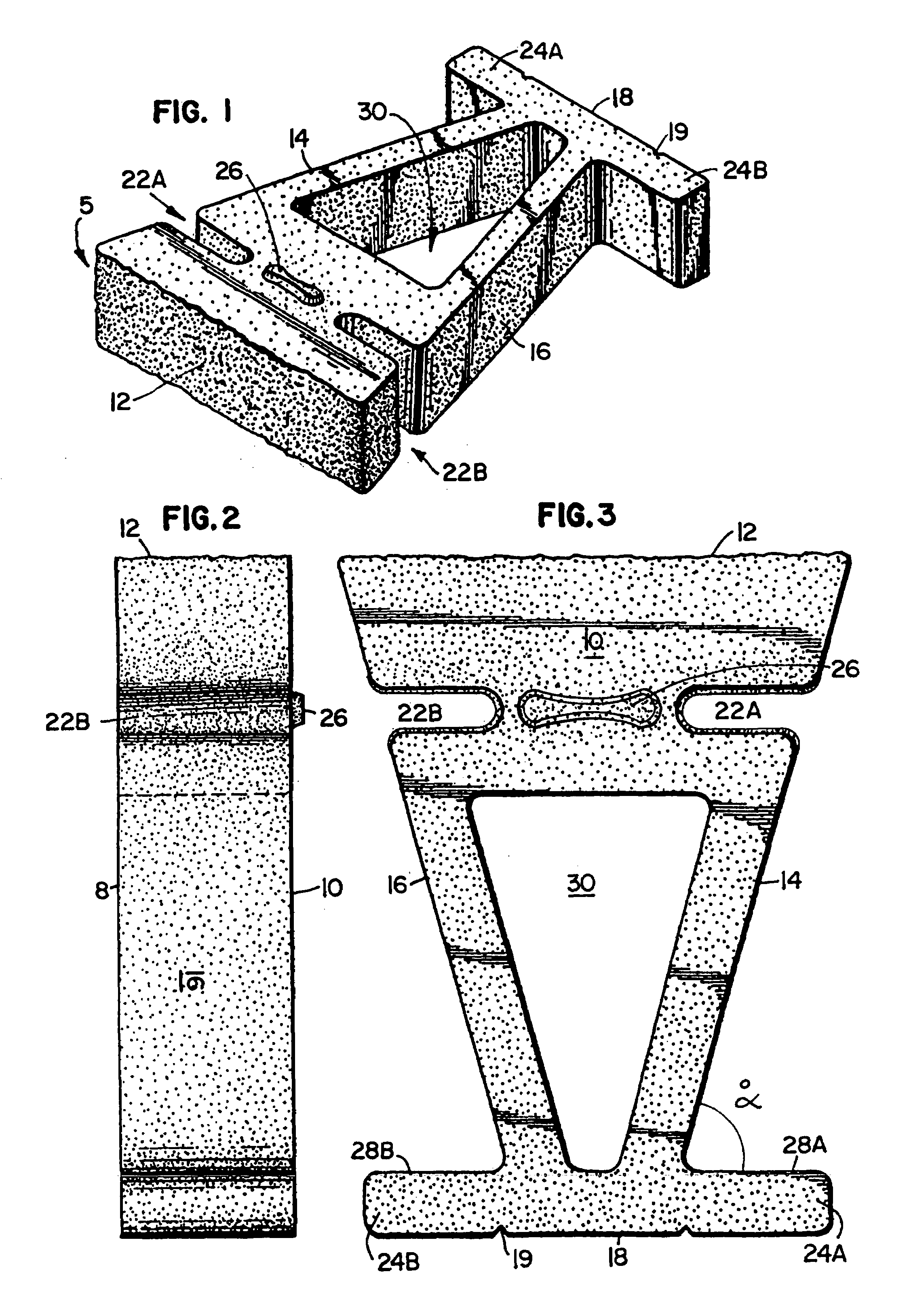
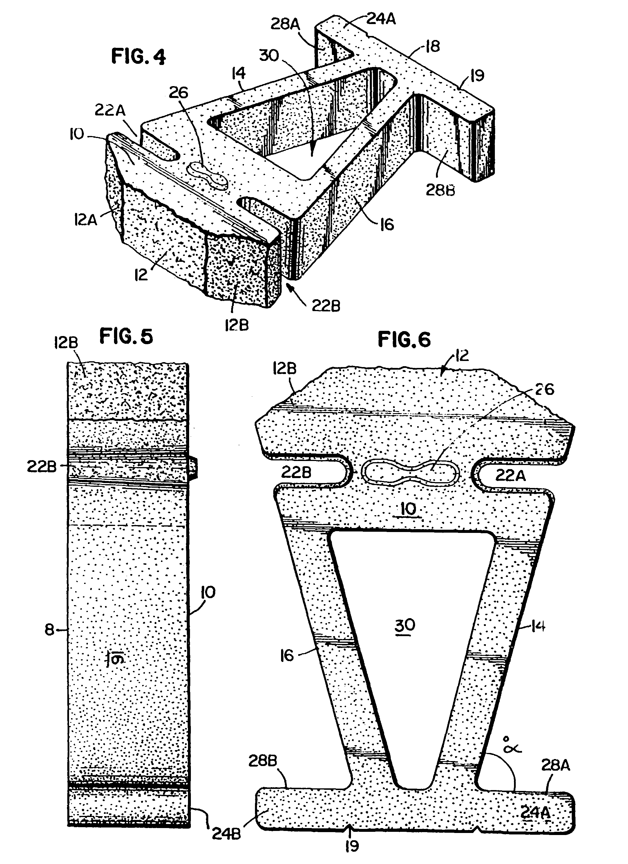
[0034]Turning to the figures wherein like parts are designated with like numerals throughout several views, there is shown a composite masonry block in FIG. 1. The block generally comprises a front surface 12 and a back surface 18 adjoined by first and second side surfaces 14 and 16, respectively, as well as a top surface 10 and a bottom surface 8 each lying adjacent said front 12, back 18, and first 14 and second 16 side surfaces. Each of said side surfaces has an inset, 22A and 22B, spanning from the block top surface 10 to the block bottom surface 8. The block top surface 10 may also comprise one or more protrusions 26. Each protrusion is preferably positioned adjacent an inset 22A or 22B, on the block top surface 10.
[0035]The block generally comprises first and second legs 24A and 24B, respectively. The first leg 24A extends from the block first side 14. The second leg 24B extends from the block second side 16.
[0036]The composite masonry block of the invention generally comprise...
PUM
Abstract
The invention is a composite masonry block having a front surface and a back surface which are adjoined by first and second side surfaces, as well as a top surface and a bottom surface. Each of the side surfaces has an inset extending from the block top surface to the block bottom surface. The block top surface has one or more protrusions positioned adjacent the first and second insets on the block top surface. The block also has a protrusion which has an angled side wall, the angle being at least about 20° from vertical. The protrusion is positioned on the block so that it will mate with any opening of an adjacently positioned course. In use, the blocks may be stacked to provide an interlocking structure wherein the protrusions of one block interfit or mate within the insets of another block.
Description
[0001]This application is a continuation of application Ser. No. 09 / 988,983, filed Nov. 19, 2001 now U.S. Pat. No. 6,641,334 which is a continuation of application Ser. No. 09 / 630,978, filed Aug. 2, 2000 (now abandoned), which is a continuation of application Ser. No. 09 / 131,084, filed Aug. 7, 1998, now U.S. Pat. No. 6,113,318, which is a continuation of application Ser. No. 08 / 474,097, filed Jun. 7, 1995, now U.S. Pat. No. 5,795,105, which is a continuation-in-part of application Ser. No. 08 / 130,298, filed Oct. 1, 1993, now abandoned, which is a continuation-in-part of application Ser. No. 08 / 056,986, filed May 4, 1993, now abandoned, which is a continuation-in-part of application Ser. No. 07 / 957,598, filed Oct. 6, 1992, now abandoned, which applications are incorporated herein by reference.FIELD OF THE INVENTION[0002]The invention generally relates to concrete masonry blocks. More specifically, the invention relates to concrete masonry blocks which are useful in forming various re...
Claims
Application Information
Patent Timeline
Application Date:The date an application was filed.
Publication Date:The date a patent or application was officially published.
First Publication Date:The earliest publication date of a patent with the same application number.
Issue Date:Publication date of the patent grant document.
PCT Entry Date:The Entry date of PCT National Phase.
Estimated Expiry Date:The statutory expiry date of a patent right according to the Patent Law, and it is the longest term of protection that the patent right can achieve without the termination of the patent right due to other reasons(Term extension factor has been taken into account ).
Invalid Date:Actual expiry date is based on effective date or publication date of legal transaction data of invalid patent.