
Anchoring drill bit, system and method of anchoring

a drill bit and anchoring technology, applied in the field of anchoring drill bit, system and method of anchoring, can solve the problems of damage to the surface of the concrete, and damage to the surface of the concrete, and achieve the effect of low cos

Inactive Publication Date: 2008-06-10
NADLER DONALD S
View PDF75 Cites 8 Cited by
  • Summary
  • Abstract
  • Description
  • Claims
  • Application Information

AI Technical Summary

Benefits of technology

[0009]An object of the instant invention is to provide a system, apparatuses and methods for anchoring, particularly into materials that are relatively brittle under tension, such as concrete, stone, masonry and cementuous materials. Another object of the instant invention is to provide a system, apparatuses and methods for anchoring that are low cost. Another object of the instant invention is to provide a system, apparatuses and methods for anchoring, particularly into concrete and other “brittle” materials, which can be removed without causing spawling to the surface.
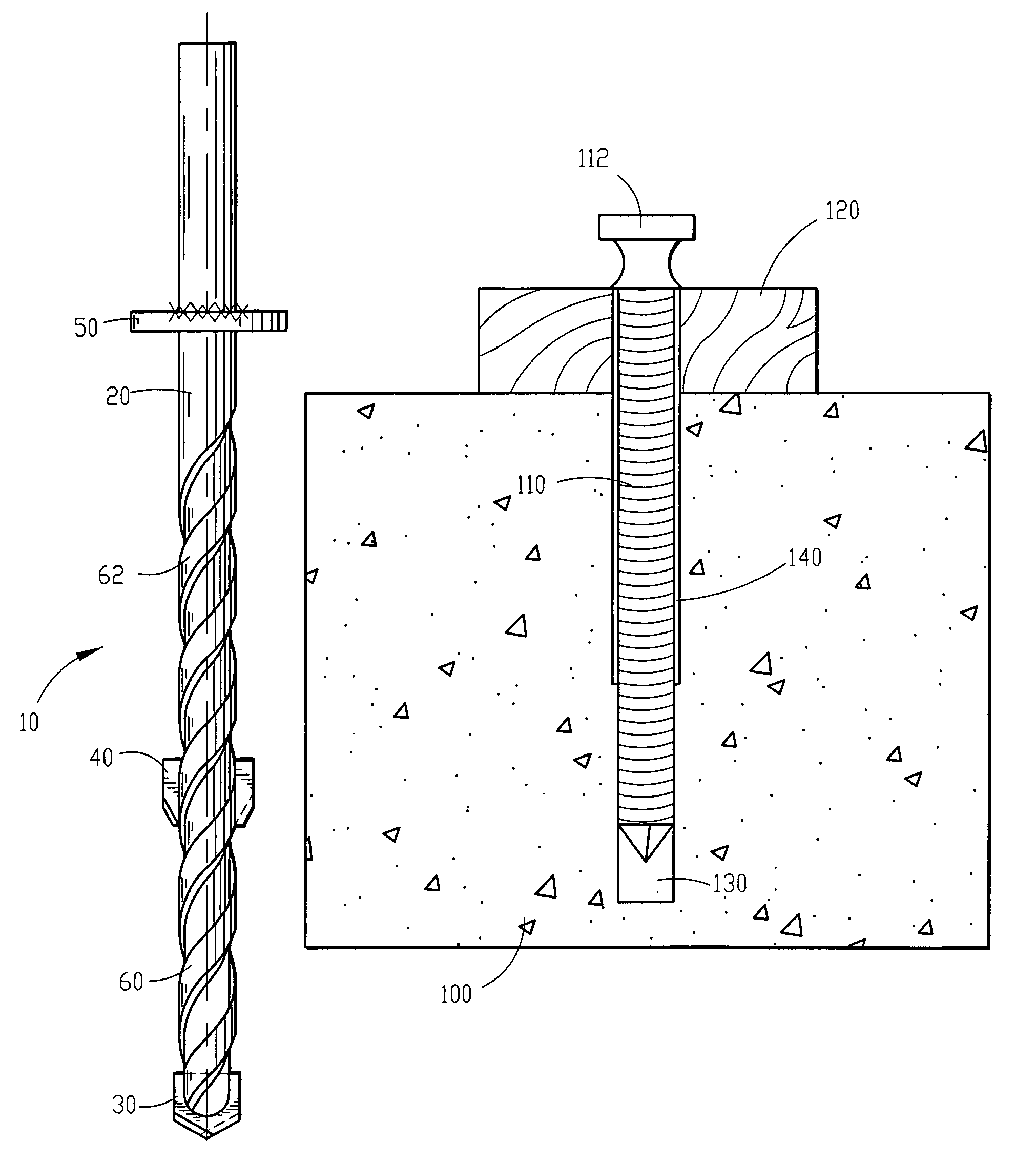
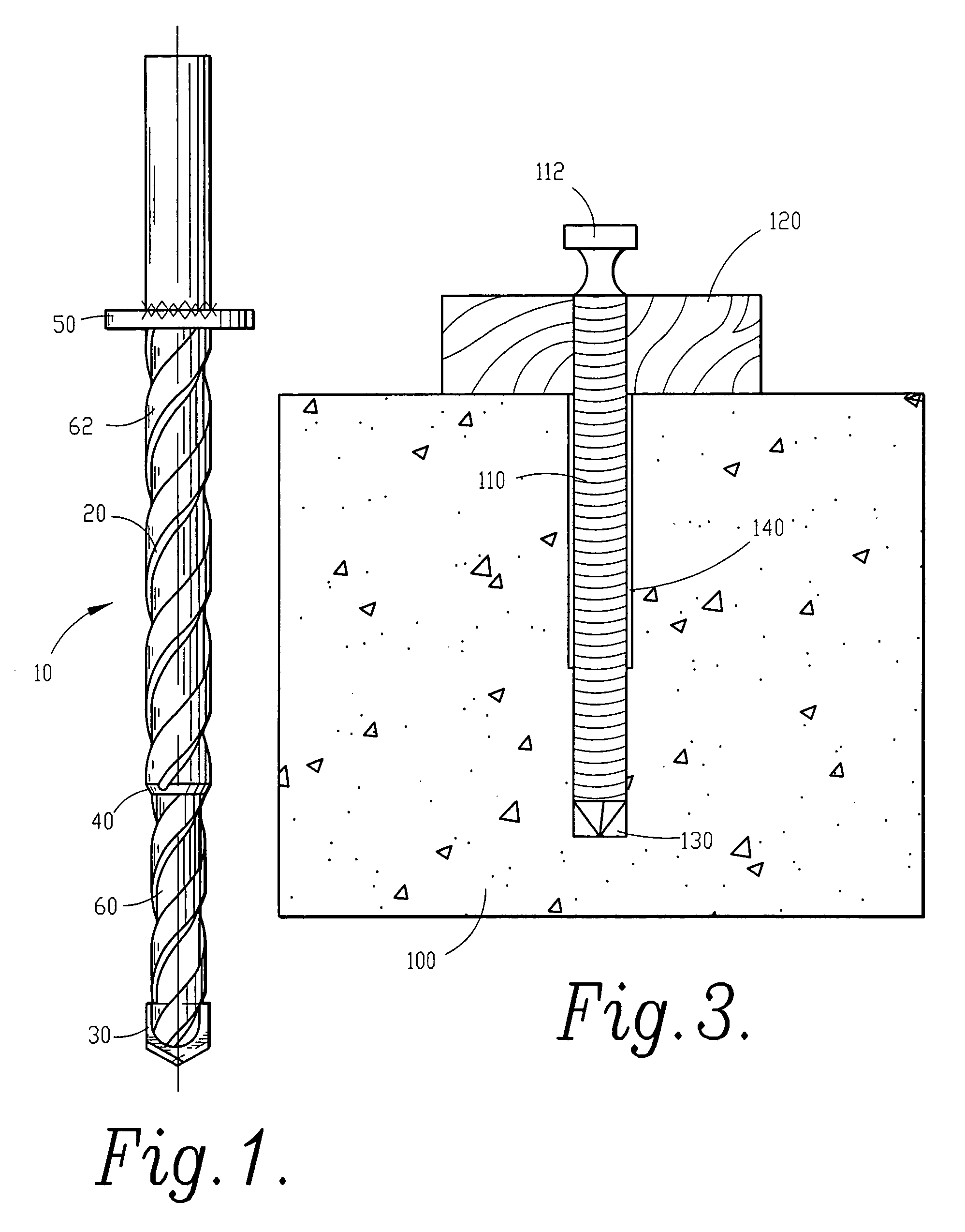
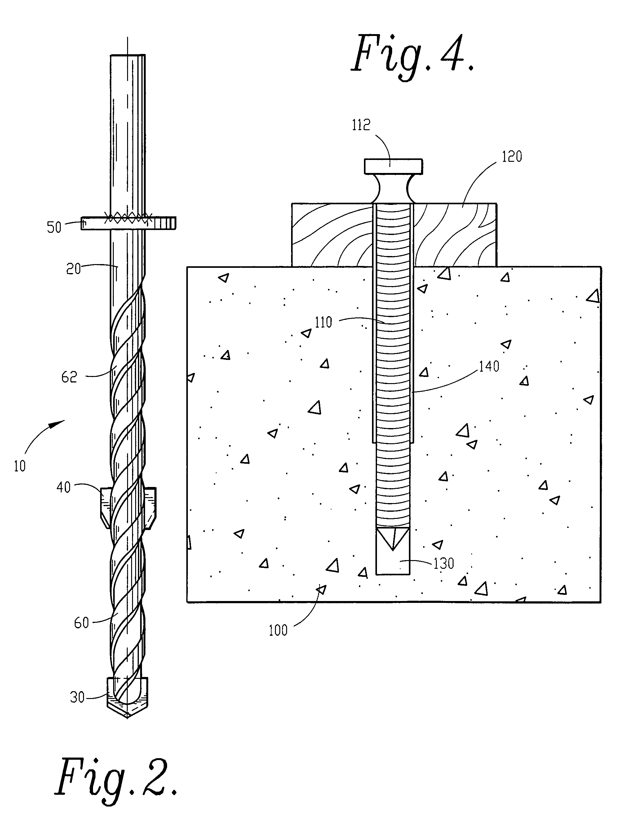
[0012]The preferred embodiment of the anchoring system and methods of the instant invention utilize the two stage bit discussed above. In the method of the instant invention, the object that is to be anchored, such as a wooden form, reveal or the like, is placed on a concrete surface. A first hole is then drilled through the form and into the concrete to a first depth. A second hole of a diameter larger than the diameter of the first hole, and having the same center point as the first hole, is drilled to a second depth that is less than the first depth (although the terms first and second are used to describe the holes of the instant invention, it will be appreciated that the order of drilling the holes of the instant invention can be reversed without departing from the scope of the invention; however it is appreciated that by drilling the narrower hole first, the wider hole can be automatically centered). A standard nail is then driven through the hole in the form that is being anchored and into the hole in the concrete. The diameter of the first hole is slightly smaller than, equal to, or slightly larger than, the diameter of the nail shank so as to provide a desired frictional fit between the nail and the concrete. The diameter of the second hole is larger than the diameter of the nail shank, such that relief is provided between the surface of the nail shank and the circumference of the second hole at the concrete surface. The diameter of the second hole is less than the diameter of the head of the nail so as to prevent the nail head from being driven into the hole drilled in the form. The depth of the second hole can be varied to provide the desired amount of frictional force to the nail when located in the hole. Increasing the depth of the second hole increases the size of the relief, reducing the frictional force on the nail. Alternatively, decreasing the depth of the second hole decreases the size of the relief, increasing the frictional force on the nail. When the form is desired to be removed the nail is removed with a hammer or a crow bar. Because the shank of the nail never contacts the circumference of the second hole, which extends to the surface of the concrete, no spawling will occur. The holes can easily be filled with concrete patch. In some instances, the clean edges of the holes do not even need to be patched, as the clean edges do not result in an unattractive surface.
[0013]The instant invention results in a significant time savings over the anchoring systems of the prior art. In the instant invention, all that is required to install and anchor is the drilling of a two-stage pilot hole and driving a standard nail into the hole. This results in substantial time savings over prior art systems that require insertion of a separate softer material into the hole and over systems that require an anchor be screwed into the concrete. The removal, or tear down, or anchors of the instant invention, which requires only the use of a crow bar, provides significant time savings over removal of the screw anchors of the prior art, and eliminates spawling caused sometimes by screw anchors and almost always by nail anchor systems of the prior art. In addition to the significant time savings for both installation and tear down of the anchors, the instant invention also results in a substantial cost savings and convenience. The instant invention utilizes standard nails that are already purchased in bulk at low cost by most contractors. The contractors do not need to purchase any special tools, other than the inventive drill bit, to install and remove the anchors; instead the contractor merely uses a common hammer and / or crow bar. In addition, the life of the contractor's drill will be increased significantly as it is not being used for high torque driving and reversing of screws.

Problems solved by technology

Thus, the removal of such permanent anchors from the concrete will undoubtedly result in damage to the surface of the concrete.
A common problem with such applications is that the surface of the concrete is usually damaged as the nail is removed from the concrete.
The most common type of damage to the surface of the concrete is known as spawling, which is caused when the surface of the concrete surrounding the pilot hole is pulled upward by friction with the nail as the nail is pulled upward and breaks away leaving an indentation or pit in the surface of the concrete.
Spawling in a concrete surface is undesirable as it creates an unattractive surface and patching a spawled surface is difficult as the patch will usually flake off.
Insertion of the softer material is extremely time consuming and requires that the contractor have an ample supply of the material on hand.
Furthermore, spawling often still occurs when the nail is removed, as the softer material is usually located on one side of the nail and the opposite side is pressed up against the concrete.
When the nail is removed, spawling occurs on the side of the concrete which the nail is pressed against.
Such specially designed nails are extremely expensive when compared to standard nails, and also result in the same one-sided spawling discussed above.
While this system does reduce spawling to the concrete surface when the screw can be reversed out of the pilot hole, some spawling often does still occur when the screw is reversed, and a number of other disadvantages exist.
Screws are relatively expensive (approx.
The wear on the contractor's drill is significant as it is used not only to drill the pilot hole, which necessitates very little torque, but also to drive and reverse the screw, which necessitates considerable torque.
The time requirement of driving and reversing the screws is significant.
In addition, the heads of the screws often strip out, making reversal of the screws impossible and resulting in substantial spawling to the concrete surface when the screw must be forcefully extracted from the concrete.

Method used


Image

  • Anchoring drill bit, system and method of anchoring
  • Anchoring drill bit, system and method of anchoring
  • Anchoring drill bit, system and method of anchoring

Examples


Embodiment Construction

[0026]As required, a detailed embodiment of the present inventions is disclosed herein; however, it is to be understood that the disclosed embodiment is merely exemplary of the principles of the invention, which may be embodied in various forms. Therefore, specific structural and functional details disclosed herein are not to be interpreted as limiting, but merely as a basis for the claims and as a representative basis for teaching one skilled in the art to variously employ the present invention in virtually any appropriately detailed structure.

[0027]Referring to FIG. 1 a front sectional view of one embodiment of a two-stage drill bit of the instant invention is shown in which drill bit 10 includes shank / shaft 20, first stage cutter 30 on shaft 20, second stage cutter 40 on shaft 20 spaced apart from first stage cutter 30, and depth gage 50 on shaft 20 spaced apart from second stage cutter 40 in a direction opposite first stage cutter 30. As is shown in FIG. 1, first stage cutter 30...


PUM


Abstract

A system, apparatuses and methods for anchoring are provided. The system includes two-stage drill bit and a method of anchoring into a two-stage hole drilled by the drill bit. The apparatus of the instant invention includes a two-stage drill bit for drilling a pilot hole for a common nail into a material such as concrete, stone, masonry or cementuous or other materials. The method of the instant invention includes the steps of drilling a first hole within a material to which an object is to be anchored, drilling a second hole concentric with the first hole, and placing an anchor within the holes.

Description

[0001]This application claims priority pursuant to 35 U.S.C. 119(e) to co-pending U.S. Provisional Patent Application Ser. No. 60 / 519,223, filed Nov. 12, 2003, the entire disclosure of which is incorporated herein by reference.FIELD OF THE INVENTION[0002]The present invention relates generally to systems, apparatuses and methods for anchoring. More particularly, the present invention is concerned with a two-stage drill bit and a method for anchoring into brittle materials such as concrete, stone, masonry and cementuous materials using a common nail.BACKGROUND OF THE INVENTION[0003]In construction applications it is often necessary or desirable to anchor into an existing concrete structure. In many construction applications the anchor is intended to be permanent to tie in a newer structure with an existing concrete structure. In such permanent anchoring applications, removal of the anchors is generally not a concern. Thus, the removal of such permanent anchors from the concrete will ...

Claims


Application Information

Patent Timeline
Patent Type & Authority Patents(United States)
IPC IPC(8): B23D77/00B23B49/00B23B51/08B23B51/00B23B51/02B23B51/10E21B10/44
CPCB23B49/005B23B51/02B23B51/009B23B2251/204B23B2251/50B23B2251/54B23B2260/0485B23B2270/54Y10T408/8925B23B2226/75B23B2240/08B23B2251/04B23B2251/14Y10T408/906B23B51/0411
Inventor NADLER, DONALD S.
Owner NADLER DONALD S
Learn More