Composite blade

a technology of composite blades and blades, applied in the field of composite blades, can solve the problems of affecting the aerofoil shape of the aerofoil, affecting the performance of the blade, and requiring a compromise of the aerofoil

Inactive Publication Date: 2008-06-10
ROLLS ROYCE PLC
View PDF17 Cites 42 Cited by
  • Summary
  • Abstract
  • Description
  • Claims
  • Application Information

AI Technical Summary

Benefits of technology

[0034]FIG. 6 is an asymmetric arrangement of the reinforcing fibres for use in the composite blade according to the present invention.
[0035]FIG. 7 is another asymmetric arrangement of the reinforcing fibres for use in the composite blade according to the present invention.
[0036]FIG. 8 is a further arrangement of the reinforcing fibres for use in the composite blade according to the present invention.
[0037]FIG. 9 is an alternative asymmetric arrangement of the reinforcing fibres for use in the composite blade according to the present invention.
[0038]FIG. 10 is a further alternative arrangement of the reinforcing fibres for use in the composite blade according to the present invention.

Problems solved by technology

A fan blade, may be optimised for take off conditions, or for cruise conditions, but to perform adequately for both take off conditions and cruise conditions generally requires a compromised aerofoil shape.

Method used


Image

  • Composite blade
  • Composite blade
  • Composite blade

Examples


Embodiment Construction

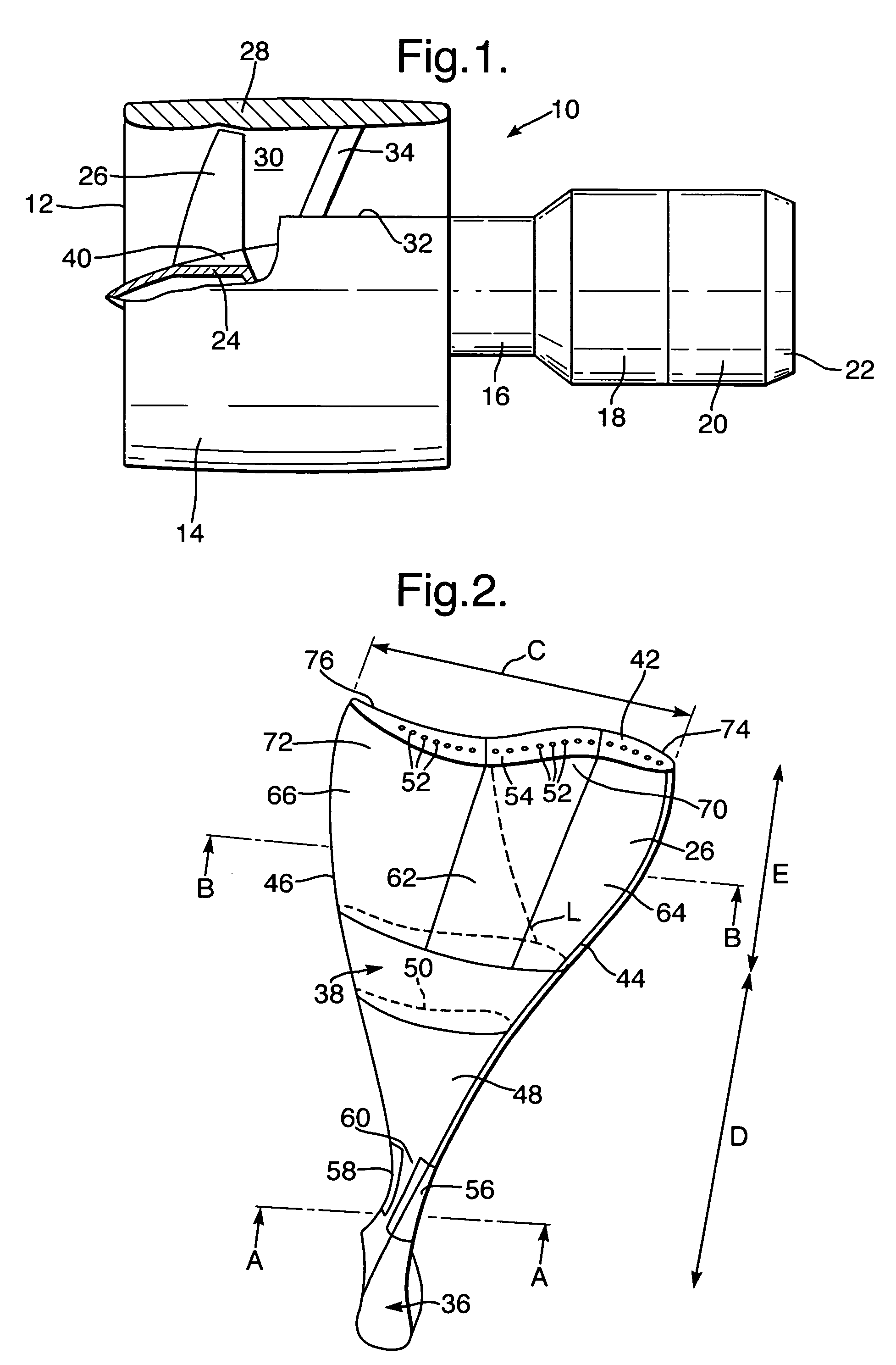
[0042]A turbofan gas turbine engine 10, as shown in FIG. 1, comprises in flow series an intake 12, a fan section 14, a compressor section 16, a combustion section 18, a turbine section 20 and an exhaust 22. The fan section 14 comprises a fan rotor 24 and a plurality of circumferentially spaced radially outwardly extending fan blades 26 secured to the fan rotor 24. The fan section 14 also comprises a fan casing 28, which surrounds the fan rotor 24 and fan blades 26 and the fan casing 28 partially defines a fan duct 30. The fan casing 28 is secured to a core casing 32 by a plurality of circumferentially spaced radially extending fan outlet guide vanes 34.

[0043]The turbofan gas turbine engine 10 is quite conventional and its operation and construction will not be discussed further.

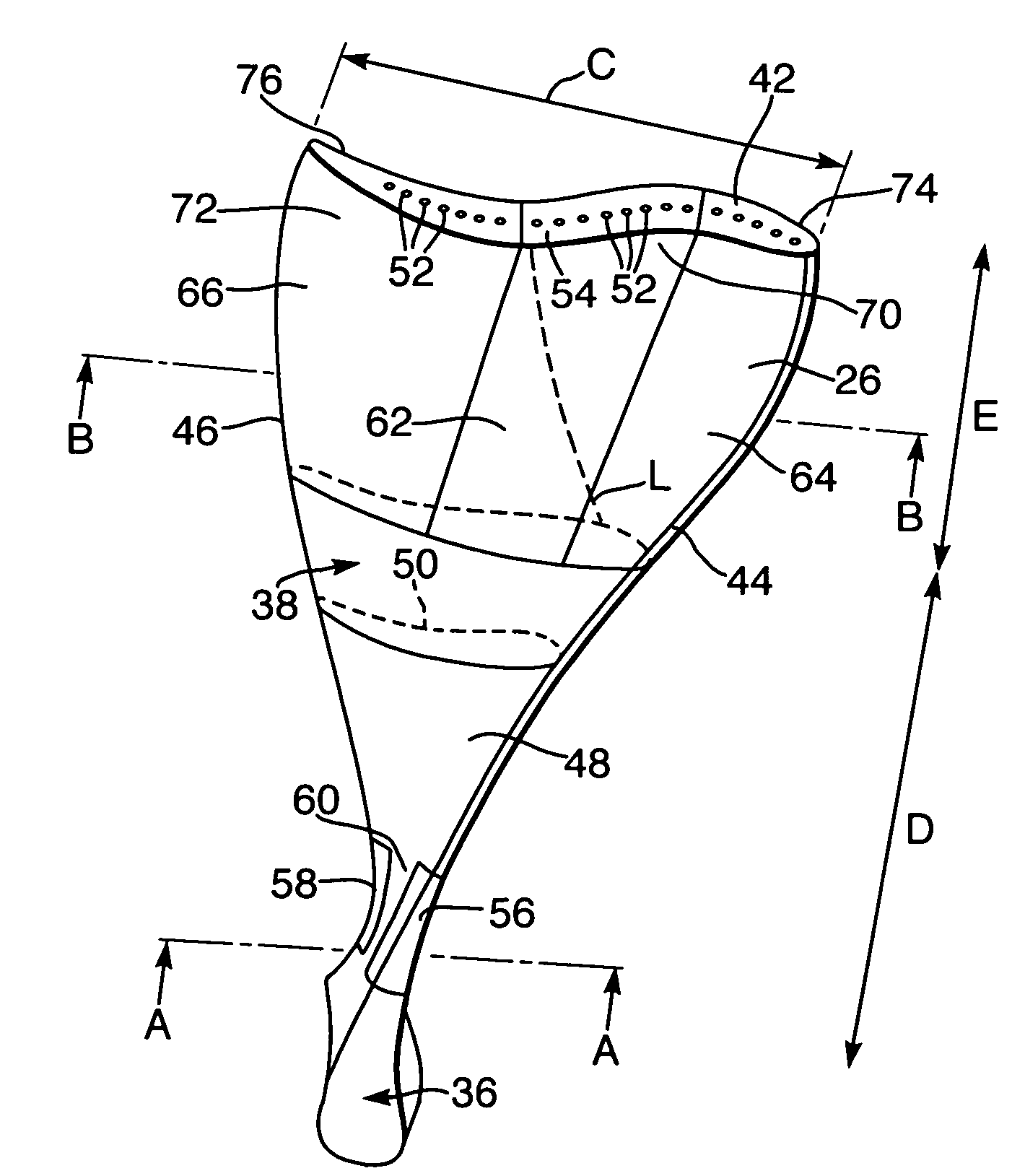
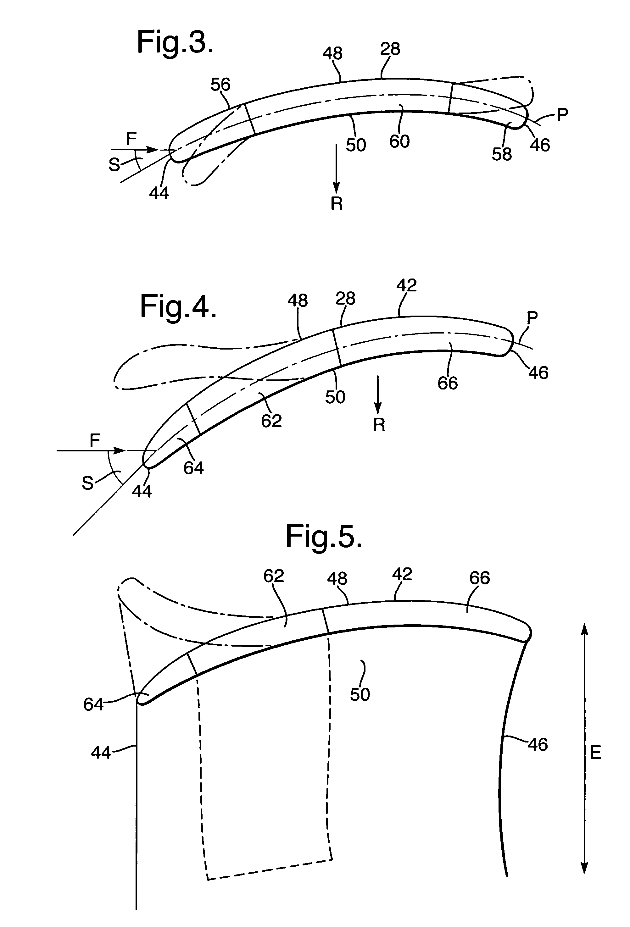
[0044]A fan blade 26 is shown more clearly in FIGS. 2, 3, 4 and 5. The fan blade 26 comprises a root portion 36 and an aerofoil portion 38. The root portion 36 is preferably dovetail shape in cross-section, b...


PUM

PropertyMeasurementUnit
pressureaaaaaaaaaa
twist angleaaaaaaaaaa
organicaaaaaaaaaa

Abstract

A composite blade (26) comprises a root portion (36) and an aerofoil portion (38). The aerofoil portion (38) has a tip (42), a chord (C), a leading edge (44), a trailing edge (46), a suction surface (48) extending from the leading edge (44) to the trailing edge (46) and a pressure surface extending from the leading edge (44) to the trailing edge (46). The composite blade (26) comprises reinforcing fibres (52) in a matrix material (54). The aerofoil portion (38) adjacent the root portion (36) has regions (56, 58) at least at the leading edge (44) and trailing edge (46) comprising an asymmetric lay up of reinforcing fibres (52) and the aerofoil portion (38) adjacent the tip (42) having at least a region (62) at the mid-chord comprising an asymmetric lay up of reinforcing fibres (52).

Description

FIELD OF THE INVENTION [0001]The present invention relates to a composite blade and in particular to a composite compressor blade, a composite fan blade, a composite propeller blade or a composite turbine blade for a gas turbine engine.BACKGROUND OF THE INVENTION[0002]It is known that different aerofoil shapes for fan blades, or compressor blades, perform differently at different operating conditions. A fan blade, may be optimised for take off conditions, or for cruise conditions, but to perform adequately for both take off conditions and cruise conditions generally requires a compromised aerofoil shape. The compromise to the aerofoil shape is based upon the mission that a particular gas turbine engine is to perform, for example whether the gas turbine engine is for long distance flight, short distance flight etc.[0003]A fan blade, or a compressor blade, generally comprises a twisted aerofoil, e.g. the stagger angle increases from the root to the tip of the aerofoil portion of the f...

Claims


Application Information

Patent Timeline
Patent Type & Authority Patents(United States)
IPC IPC(8): B64C11/28F01D5/14F01D5/28F04D29/38
CPCF01D5/147F01D5/148F01D5/282F04D29/382F04D29/388B29K2105/06B29L2031/08Y02T50/672Y02T50/673F05D2300/505Y02T50/60
Inventor MCMILLAN, ALISON JJACKSON, ANDREW D
Owner ROLLS ROYCE PLC
Why Eureka
Try Eureka