Pre-converter device for cleaning exhaust gas for an internal combustion engine

Inactive Publication Date: 2008-06-10
BRP ROTAX
View PDF15 Cites 7 Cited by
  • Summary
  • Abstract
  • Description
  • Claims
  • Application Information

AI Technical Summary

Benefits of technology

[0012]In accordance with one aspect of embodiments of the present invention, a catalytic converter device for cleansing exhaust gas emitted from an internal combustion engine is disclosed. While the catalytic converter device is preferably a pre-converter, the catalytic device can be a primary or main catalytic converter device as well. The converter device includes an elongated body having a longitudinal axis. An inlet area is located at one end of the elongated body. The exhaust gas from the internal combustion engine enters the elongated body in the inlet area. A sleeve extends from the inlet area. The sleeve has a catalytic material formed thereon. The sleeve has an active surface for reacting with the exhaust gas. The size of the active surface increases as a distance from the inlet area increases, whereby provides a greater surface for reaction with the exhaust gas to improve the conversion of the unburned hydrocarbons and pollutants.
[0013]The sleeve has a plurality of openings formed therein to permit the exhaust gas to flow there through. The plurality of openings extend across the active surface. The sleeve can include at least one depression formed therein, which increases the amount of active surface area within the pre-converter for reacting with the unburned hydrocarbons and pollutants. The depression(s) can extend substantially parallel to the longitudinal axis of the body. The sleeve without a depression has a first internal cross section. The sleeve having the at least one depression has a second internal cross section. The second internal cross section is smaller than said first internal cross section. The second internal cross section changes as the distance from the inlet area increases. Each depression has a depth. In accordance with embodiments of the present invention, the depth of the depression can increase as the distance from the inlet area increases.
[0015]The preliminary converter device can include an elongated body having a longitudinal axis. An inlet area is located at one end of the elongated body. The exhaust gas from the internal combustion engine enters the elongated body in the inlet area. A sleeve extends from the inlet area. The sleeve has a catalytic material formed thereon. The sleeve has an active surface for reacting with the exhaust gas. The size of the active surface increases as a distance from the inlet area increases, whereby provides a greater surface for reaction with the exhaust gas to improve the conversion of the unburned hydrocarbons and pollutants.

Problems solved by technology

These requirements cannot be met unless the catalytic converter can become quickly operational (i.e., rapidly heated).
This location of the converter, however, impairs the functional performance of the exhaust system because of the amount of space occupied by the converter.
The reduction in performance of the exhaust system has a direct impact on engine performance including a deterioration of the power, a reduction in the torque delivered, and an increase in fuel consumption.
Furthermore, the close proximity of the converter to the engine cylinders can cause undesired reactions on the cylinder.
These devices have been found to be inefficient and inadequate in treating the gas.
In particular, these devices do not account for the expansion of the exhaust gas as it is heated while passing through the catalyst.
Locating the pre-converter in too close a proximity to the cylinder will produce the above-described reduction in engine performance.
The location of this pre-converter suffers from many of the above-described drawbacks including an adverse impact on engine performance.
Furthermore, the pre-converter extends across the entire cross-section of the exhaust system, which adversely impacts the flow dynamics of the exhaust gases within the exhaust system and performance.
The location of this pre-converter adversely impacts engine performance.

Method used


Image

  • Pre-converter device for cleaning exhaust gas for an internal combustion engine
  • Pre-converter device for cleaning exhaust gas for an internal combustion engine
  • Pre-converter device for cleaning exhaust gas for an internal combustion engine

Examples


Embodiment Construction

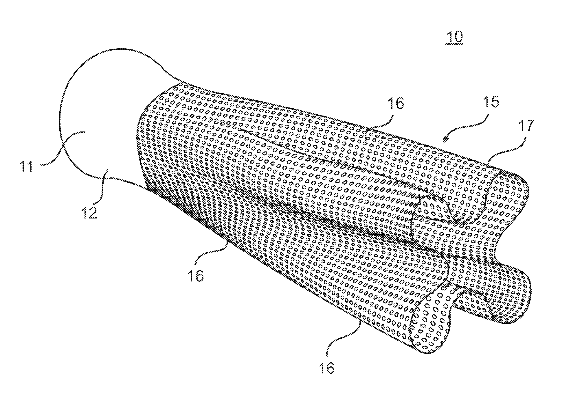
[0026]A pre-converter 10 according to an embodiment of the present invention is illustrated in FIG. 1. The pre-converter 10 is adapted to be incorporated into an exhaust system 20 for an internal combustion engine. The internal combustion engine can be either a two-stroke engine or a four-stroke engine. The engine can have one or more cylinders. It is contemplated that the internal combustion engine containing the pre-converter 10 can be used to supply power to a snowmobile, a personal watercraft, a motorcycle, a three-wheeled vehicle, a go-kart, an all-terrain vehicle, or an outboard engine for use on a boat.

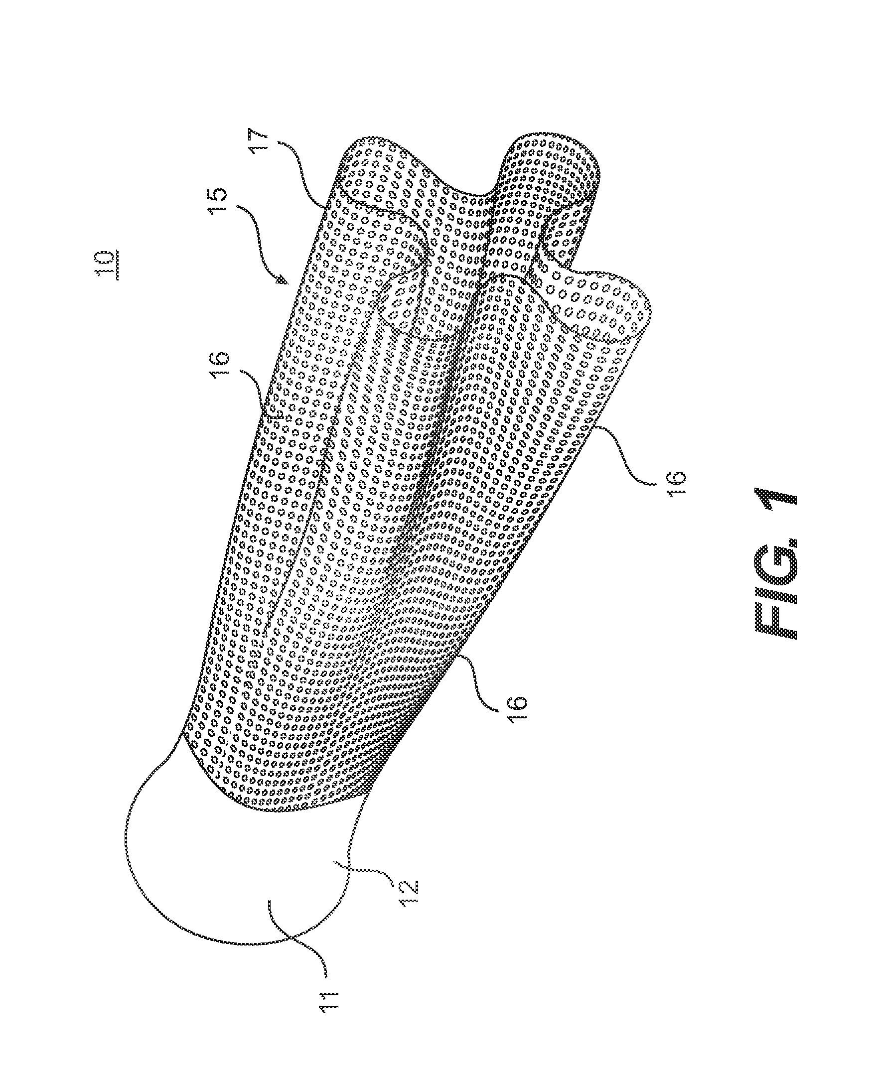
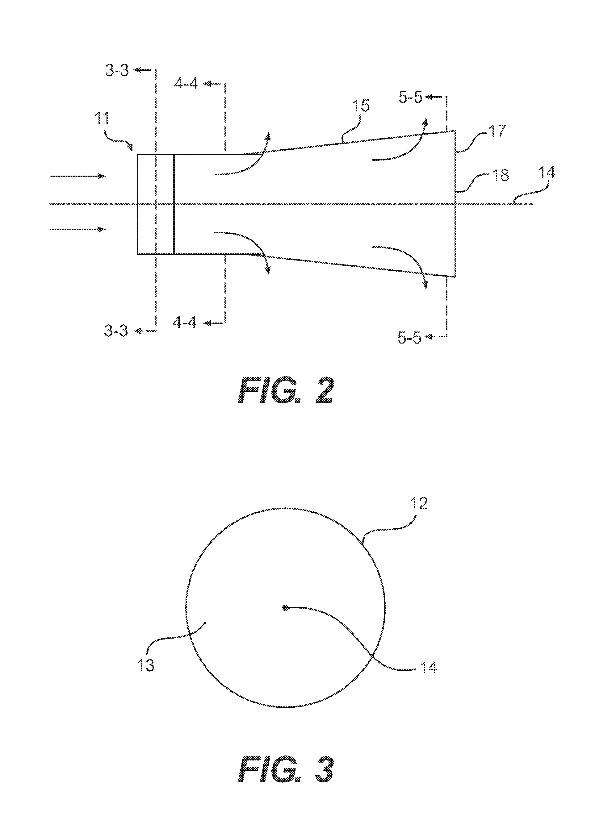
[0027]The pre-converter 10 has an elongated body, as shown in FIGS. 1, 2 and 6 having an inlet area 11 located on one end. Exhaust gases from the engine cylinders are introduced into the pre-converter 10 through the inlet area 11. The inlet area 11 preferably has a solid wall 12 such that is can be connected to the exhaust system 20 to prevent leakage of exhaust gas. The inlet ...


PUM

PropertyMeasurementUnit
Fractionaaaaaaaaaa
Diameteraaaaaaaaaa
Widthaaaaaaaaaa

Abstract

A catalytic converter device for cleansing exhaust gas emitted from an internal combustion engine is disclosed. The catalytic converter device includes an elongated body having a longitudinal axis. An inlet area is located at one end of the elongated body, wherein the exhaust gas enters the elongated body in the inlet area. A sleeve extends from the inlet area. The sleeve has a catalytic material formed thereon. The sleeve has an active surface for reacting with the exhaust gas, wherein the size of the active surface increases as a distance from the inlet area increases. The sleeve includes a plurality of openings formed therein and at least one depression.

Description

CROSS REFERENCE TO RELATED APPLICATION[0001]This application relates to and claims priority to U.S. Provisional Patent Application No. 60 / 443,186, filed on Jan. 29, 2003, the contents of which are incorporated herein by reference.BACKGROUND OF THE INVENTION[0002]1. Field of the Invention[0003]The present invention relates to a preliminary catalytic converter (“pre-converter”) device for cleaning exhaust gas, that contains hydrocarbons, which are emitted from an internal combustion engine. In particular, the pre-converter device has a perforated sleeve that is coated with a catalytic material to form an active surface. The area of the active surface increases as the distances from the pre-converter inlet increases. The pre-converter device is configured such that the active surface area on the pre-converter device increases as the temperature of the exhaust gases within the pre-converter device increases and the gas expands.[0004]2. Description of Related Art[0005]The typical operati...

Claims


Application Information

Patent Timeline
IPC IPC(8): B01D53/34F02K1/00B01D50/00B01D53/94F01N1/00F01N3/08F01N3/20F01N3/28
CPCB01D53/94F01N3/2803F01N3/2821
Inventor ZAUNER, GUNTER
Owner BRP ROTAX
Why Eureka
Try Eureka