Movable inclination-angle measuring apparatus for ion beam, and method of use

a technology of inclination angle and measuring apparatus, which is applied in the direction of heat measurement, optical radiation measurement, instruments, etc., can solve the problems of predetermined limitation of detection resolution of inclination angle of spot ion beam, difficulty in limiting the hole by the sidewall structure to a length (or diameter) smaller than 1 mm, and inability to use inclination angle measuring apparatus for spot ion beam measurement, etc., to achieve detection resolution of inclination angle and simple system construction

Inactive Publication Date: 2008-06-10
SAMSUNG ELECTRONICS CO LTD
View PDF13 Cites 8 Cited by
  • Summary
  • Abstract
  • Description
  • Claims
  • Application Information

AI Technical Summary

Benefits of technology

[0014]The present invention provides an ion beam inclination-angle measuring apparatus for an ion beam and an inclination-angle measuring method using the apparatus. The inclination-angle measuring apparatus has a simple system construction, and an inclination angle of a spot ion beam and an inclination angle of a ribbon ion beam can be measured with the same apparatus. Detection resolution for an inclination angle of an ion beam is excellent, and the measurement of the ion beam does not have a blind region.

Problems solved by technology

The inclination-angle measuring apparatus for the spot ion beam cannot be used for measuring the inclination angle of the ribbon ion beam generated by the ion implantation equipment.
For example, even if it is not impossible, it is considerably difficult to limit the hole by the sidewall structure to a length (or diameter) smaller than 1 mm.
If the hole of Faraday cup is large in size, the detection resolution of the inclination angle of the spot ion beam has a predetermined limitation.
The limitation of the detection resolution becomes an obstacle in precisely controlling the inclination angle of the ion beam.
Additionally, since the ion beam is increased in size and accordingly, a Faraday cup and its dependent hole are concurrently increased in size, the detection resolution of the inclination angle becomes worse.
Accordingly, the conventional inclination-angle measuring apparatus has a drawback in that the ribbon ion beam has a blind region between adjacent Faraday cups in which the inclination angle cannot be measured.

Method used


Image

  • Movable inclination-angle measuring apparatus for ion beam, and method of use
  • Movable inclination-angle measuring apparatus for ion beam, and method of use
  • Movable inclination-angle measuring apparatus for ion beam, and method of use

Examples


Embodiment Construction

[0024]The attached drawings for illustrating preferred embodiments of the present invention are referred to in order to gain a sufficient understanding of the present invention, the merits thereof, and the objectives accomplished by the implementation of the present invention.

[0025]Hereinafter, the present invention will be described in detail by explaining embodiments of the invention with reference to the attached drawings. Like reference numerals in the drawings denote like elements.

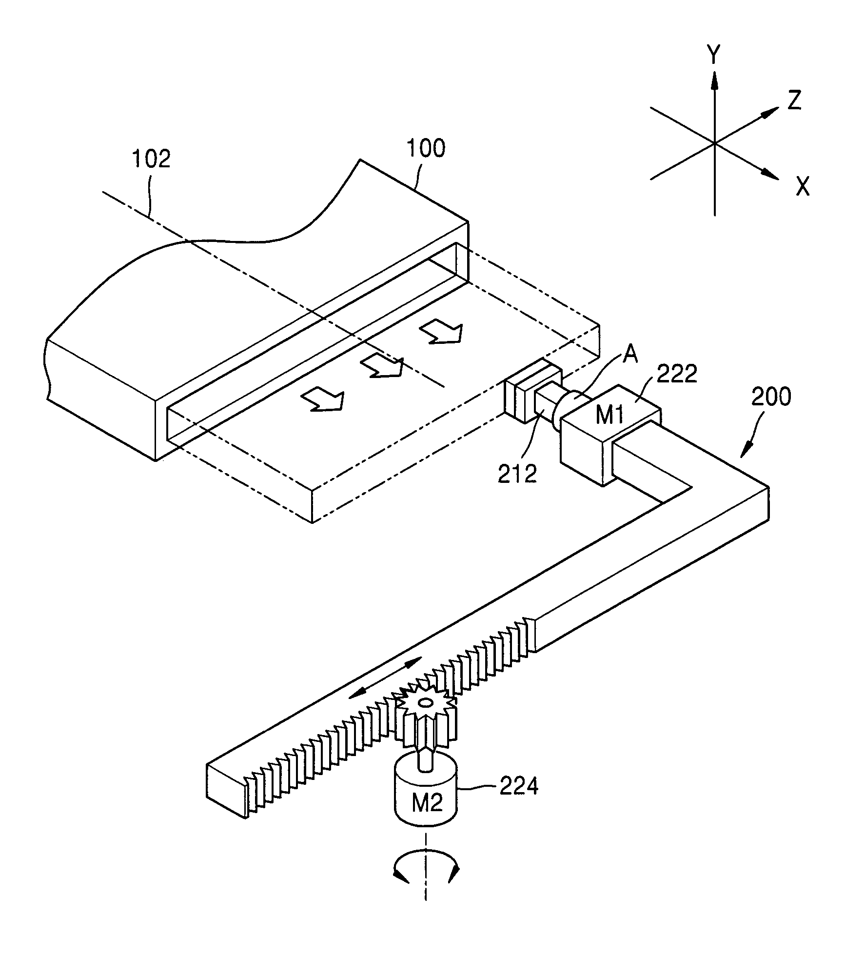
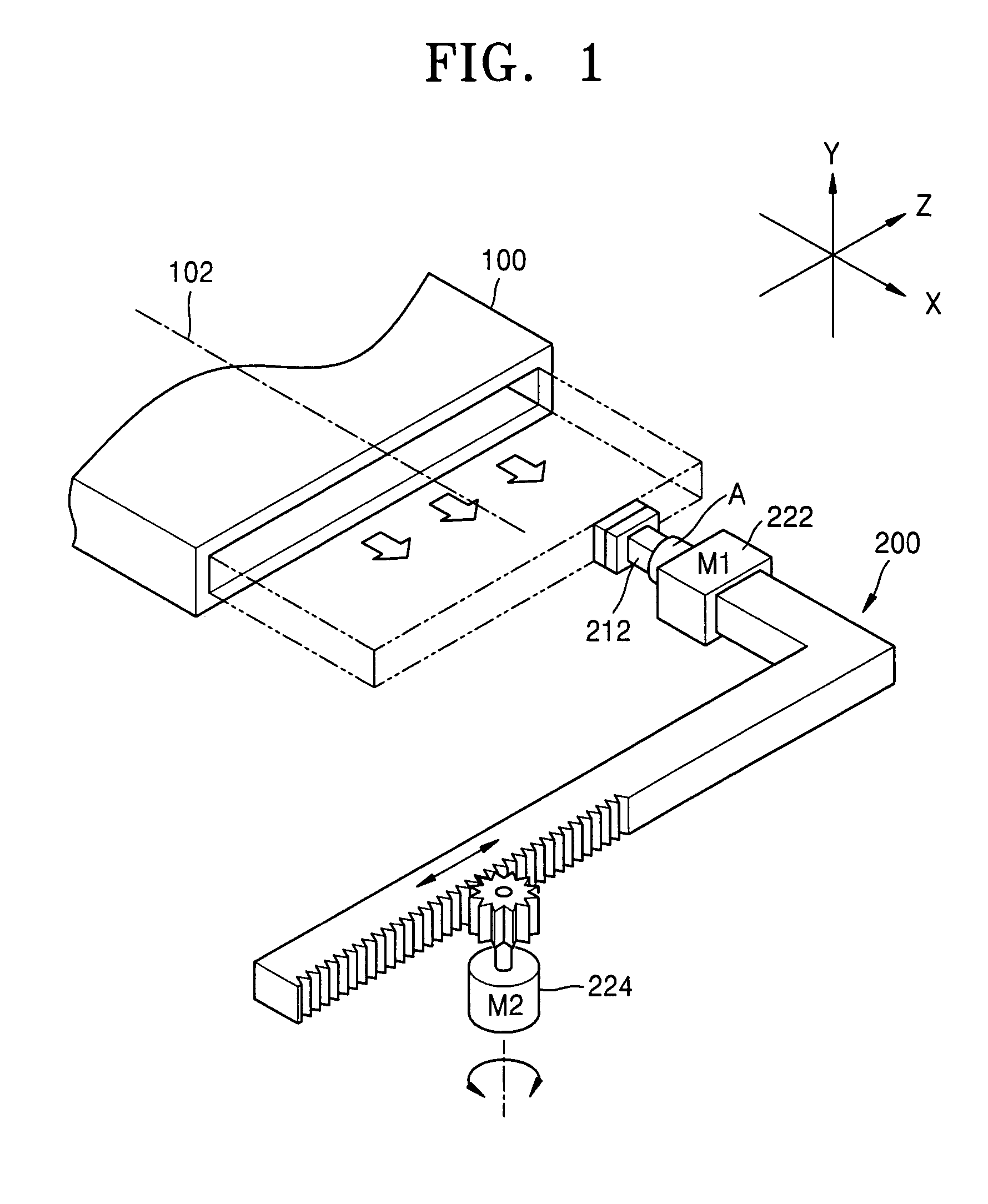
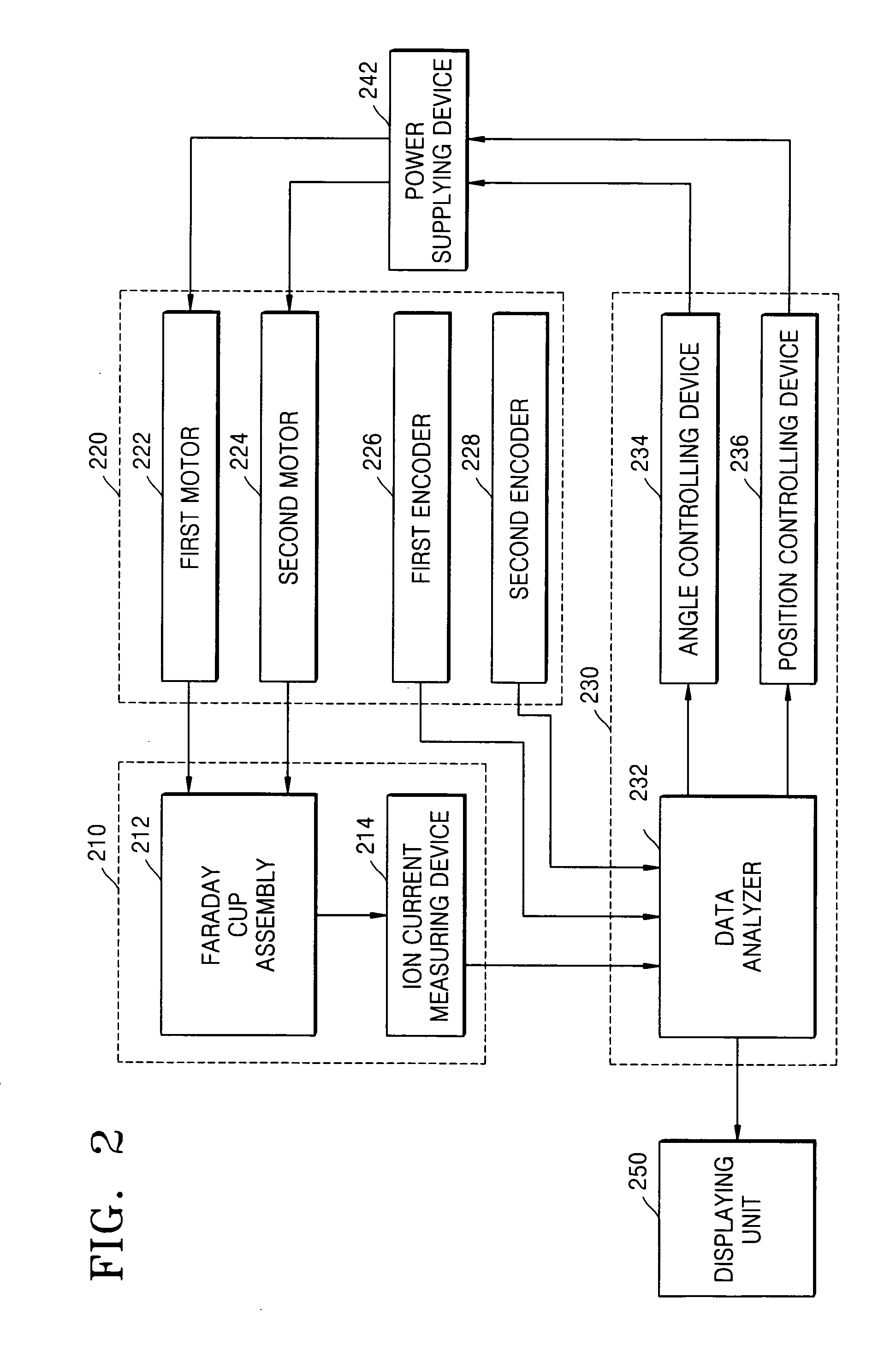
[0026]FIG. 1 is a schematic view illustrating an ion beam inclination-angle measuring apparatus according to an embodiment of the present invention. FIG. 2 is a block diagram illustrating the ion beam inclination-angle measuring apparatus of FIG. 1.

[0027]Referring to FIGS. 1 and 2, the inclination-angle measuring apparatus 200 includes: an ion current measuring unit 210; an angle adjusting unit and position adjusting unit 220; and an inclination-angle calculating unit 230. Additionally, the ion beam r...


PUM

PropertyMeasurementUnit
diameteraaaaaaaaaa
diameteraaaaaaaaaa
diameteraaaaaaaaaa

Abstract

There is provided a movable ion beam inclination-angle measuring apparatus that can measure the inclination angle of either a spot ion beam or a ribbon ion beam. The apparatus is provided in an X-axis direction from an ion supplying unit of an ion implantation device. The apparatus includes an ion current measuring unit which has an ion-beam receiving device for receiving the ion beam, and has an ion current measuring part for measuring an ion current induced by the received ion beam. The apparatus further includes an angle adjusting unit adapted to adjust a receiving angle of the ion beam receiving device about a Y-axis and / or Z-axis and a position adjusting unit adapted to move the ion-beam receiving device in a Z-axis direction. The inclination angle is calculated by an inclination-angle calculating unit using the variation of the measured ion current depending on the adjustment of the receiving angle of the ion beam.

Description

BACKGROUND OF THE INVENTION[0001]This application claims the priority of Korean Patent Application No.: 2004-32198, filed on May 7, 2004, in the Korean Intellectual Property Office, the disclosure of which is incorporated herein in its entirety by reference.[0002]1. Field of the Invention[0003]The present invention relates to an apparatus for manufacturing a semiconductor device, and more particularly, to an inclination-angle measuring apparatus for an ion beam.[0004]2. Description of the Related Art[0005]Ion implantation is a technique for ionizing and accelerating impurities in a form of an ion beam and then implanting an appropriate amount of the ionized impurities into a desired region of a semiconductor substrate, material film or the like. Ion implantation is a part of the semiconductor fabrication procedure that selectively implants high-pure impurities into the substrate. In ion implantation, the position and the implantation depth of implanted ions can be precisely controll...

Claims


Application Information

Patent Timeline
Patent Type & Authority Patents(United States)
IPC IPC(8): H01J37/08G01J1/00H01J37/30G01N23/00H01J37/317
CPCG01N23/00H01J2237/24507H01J2237/24528H01J37/244H01J37/08
Inventor YOON, YOUNG-HA
Owner SAMSUNG ELECTRONICS CO LTD
Why Eureka
Try Eureka