Inspection device

Active Publication Date: 2008-06-10
STRATUS VISION
View PDF3 Cites 1 Cited by
  • Summary
  • Abstract
  • Description
  • Claims
  • Application Information

AI Technical Summary

Benefits of technology

[0025]It is to be understood that the inventive tunnel need not necessarily widen conically. A cylindrical tunnel, on the inner periphery of which the illumination elements are secured, in fact makes it possible to

Problems solved by technology

The drawback of this is that almost all of the layers have to be applied, and then the testing is undertaken.
If the test shows errors, then there is only the possibility of throwing the pertaining chip away, which is accompanied by corresponding cost disadvantages.
However, with the customer requirement of a rapid and reliable tes

Method used


Image

  • Inspection device
  • Inspection device
  • Inspection device

Examples


Embodiment Construction

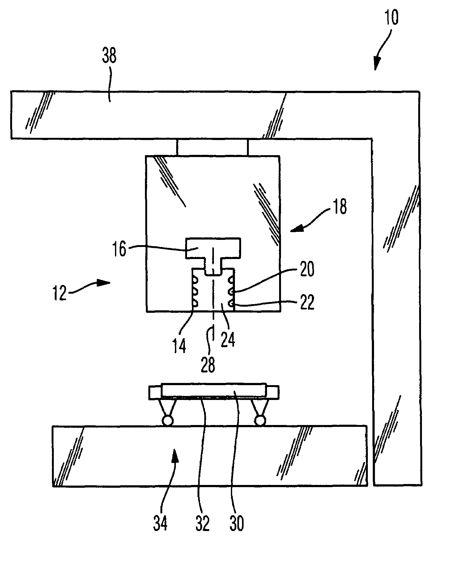
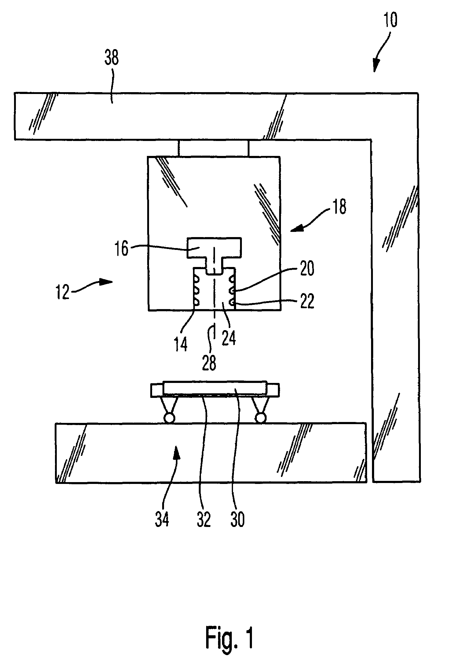
[0030]The inspection device 10 illustrated in FIG. 1 has an inspection head 12 which in turn is provided with an illumination mechanism 14 and a detection device 16.

[0031]The detection device 16 has a digital camera 18 and possibly pertaining and not-illustrated optics. The detection device is connected with a non-illustrated evaluation device that processes and evaluates the image data after conversion into electrical signals. For this purpose, a frame grabber as well as a PC are connected, whereby the PC undertakes the adjustable error evaluation.

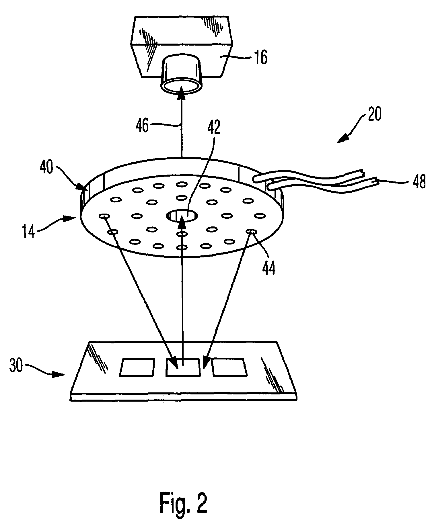
[0032]The illumination mechanism 14 comprises a plurality of light-emitting diodes 20, 22 that are preferably mounted at a slight angle and which are disposed in a tunnel 24. In the illustrated embodiment, the tunnel is cylindrical and the light-emitting diodes 20, 22 are disposed on its inner periphery in different rows or rings. Light-emitting diodes of different colors are used for the various materials that are to be detected.

[0033]An...


PUM


Abstract

A device for inspecting a substrate having at least one printed-on layer, including a guide carrier on which the substrate is supported. An inspection head is movable in at least two directions relative to the guide carrier and is provided with an illumination mechanism and an detection device for detecting electromagnetic radiation reflected from the substrate and conveying it to an evaluation device for detecting substrate errors. The detection device has a digital camera with optics for detecting a definition of less than 200 microns. A movement mechanism controls the relative movement between guide carrier and inspection head during an image-taking cycle during which sequential or overlapping individual images can be joined together to form an overall image of the substrate.

Description

[0001]This specification for the instant application should be granted the priority date of Nov. 24, 2004, the filing date of the corresponding German patent application 10 2004 056 698.4.BACKGROUND OF THE INVENTION[0002]The invention relates to an inspection device having an inspection head that is movable in at least two directions relative to a guide carrier that supports a substrate that is to be inspected, whereby the substrate has at least one printed-one layer, whereby the inspection head has an illumination mechanism and a detection device that detects the electromagnetic radiation reflected from the substrate and conveys it to an evaluation device for detecting errors of the substrate.[0003]Such an inspection device is used to test the quality of circuits that in particular are placed or deposited using thick target or layer technology. Such circuits are ordinarily applied in a plurality, for example 20, of layers via screen printing technology. In this connection, it is im...

Claims


Application Information

Patent Timeline
IPC IPC(8): G01N21/00
CPCG01R31/309G01N2021/95638G01J1/04G01R31/308
Inventor STENGER, HEINRICH
Owner STRATUS VISION
Why Eureka
Try Eureka