Method of fabricating a photomask

a technology of photomask and supplementary pattern, which is applied in the field of photomask fabrication, can solve the problems of increasing the number of supplementary pattern in the photomask, severe differences in resolution, and time waste in the fabrication of the photomask, so as to reduce the number of unnecessary microscopic supplementary patterns, reduce the cost of the product, and the effect of precise line width

Inactive Publication Date: 2008-06-10
DONGBU ELECTRONICS CO LTD
View PDF6 Cites 22 Cited by
  • Summary
  • Abstract
  • Description
  • Claims
  • Application Information

AI Technical Summary

Benefits of technology

[0008]An object of the present invention is to provide a method of fabricating a photomask, in which a microscopic supplementary pattern is automatically generated by selective sizing to reduce a product cost and by which a precise line width is provided in a manner of decreasing unnecessary microscopic supplementary patterns to raise the precision of a photomask pattern.

Problems solved by technology

Specifically, the difference in resolution is severe for a particular hole or holes in a contact hole mask.
However, since the related art method needs a supplementary pattern for controlling the optical proximity effect to overcome such a problem, time is wasted in fabricating the photomask and the number of the supplementary patterns increases in the photomask.
Hence, the precision of the photomask pattern is lowered and is not able to yield precise critical dimensions.

Method used


Image

  • Method of fabricating a photomask
  • Method of fabricating a photomask
  • Method of fabricating a photomask

Examples


Embodiment Construction

[0020]Reference will now be made in detail to the preferred embodiments of the present invention, examples of which are illustrated in the accompanying drawings. Wherever possible, the same reference numbers will be used throughout the drawings to refer to the same or like parts.

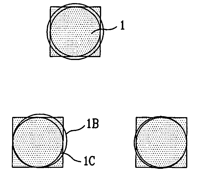
[0021]First of all, in the present invention, a microscopic supplementary pattern is separated from a main pattern to leave a prescribed distance in-between to fabricate a photomask having no line width difference between holes in sparse and dense areas. Specifically, the microscopic supplementary pattern is inserted while the distance between the main and microscopic supplementary patterns is fixed.

[0022]The microscopic supplementary pattern is a microscopic pattern having a critical dimension below a solution limit. The microscopic pattern exists on the photomask but fails to be formed on a semiconductor substrate after exposure. The pattern resolution is determined by Rayleigh's Equation of ‘R(resolution)...


PUM

PropertyMeasurementUnit
widthaaaaaaaaaa
areaaaaaaaaaaa
dimensionaaaaaaaaaa

Abstract

A method of fabricating a photomask automatically generates a microscopic supplementary pattern by selective sizing to reduce a product cost and by which a precise line width is provided in a manner of decreasing unnecessary microscopic supplementary patterns to raise precision of a photomask pattern. The method includes the steps of selectively carrying out a sizing on a main pattern to form a microscopic supplementary pattern with a difference of the corresponding sizing and selectively removing the microscopic supplementary pattern.

Description

BACKGROUND OF THE INVENTION[0001]1. Field of the Invention[0002]The present invention relates to a method of fabricating a photomask, and more particularly, to a method of fabricating a microscopic hole photomask, in which line width patterning is appropriately compensated by a supplementary pattern and by which a precise line width can be provided.[0003]2. Discussion of the Related Art[0004]Generally, a photomask pattern directly affects a precision of a real pattern formed on a semiconductor substrate. If an optical proximity effect of the photomask pattern fails to be correctly taken into consideration, a pattern line width is distorted, unlike the intended exposure of a photolithography process. Hence, line width linearity is shortened to degrade semiconductor device characteristics.[0005]In a method of fabricating a microscopic photomask according to a related art, even if design line widths, as shown in FIG. 1, are equal to each other regardless of a density of contact hole pa...

Claims


Application Information

Patent Timeline
Patent Type & Authority Patents(United States)
IPC IPC(8): G06F17/50G03F1/00H01L21/027G03F1/14G03F9/00
CPCG03F1/144G03F1/36H01L21/027
Inventor LEE, JUN SEOK
Owner DONGBU ELECTRONICS CO LTD
Why Eureka
Try Eureka