Plasma ignition system

a technology of ignition system and plasma, which is applied in the direction of spark plugs, machines/engines, mechanical equipment, etc., can solve the problems of difficult wiring of shield wires, misfire in engines, and high frequency electromagnetic noise n, and achieve the effect of less electromagnetic noise outward

Active Publication Date: 2008-06-17
DENSO CORP
View PDF9 Cites 27 Cited by
  • Summary
  • Abstract
  • Description
  • Claims
  • Application Information

AI Technical Summary

Problems solved by technology

This occurs at every predetermined rotation of the engine, and hence high frequency electromagnetic noise N is generated.
This noise is likely to cause various electronic control systems mounted in a vehicle.
This may lead to misfire in the engine.
Since the shield wire has low flexibility, wiring the shield wire becomes difficult.
If the shield wire has an imperfectly shielded part, electromagnetic noise leaks.
This shield may not be easily provided in a crowded engine compartment.
In some instances, this shield itself operates as an antenna and generates electromagnetic noise.
Further, since the stray capacitance formed between the shield and the electric wire of the plasma generating power circuit changes irregularly in accordance with bending, this may result in a new source of noise.
Further, the ignition coil and the plasma ignition plug is likely to form a transmission circuit, which generates electromagnetic noise when the ignition plug starts to discharge in response to the secondary voltage of the ignition coil.
Since a large current must flow in the electric wire, it is not possible to stop generation of electromagnetic noise, which is generated at a start of discharging, by a resistor in the electric wire.

Method used


Image

  • Plasma ignition system
  • Plasma ignition system
  • Plasma ignition system

Examples


first embodiment

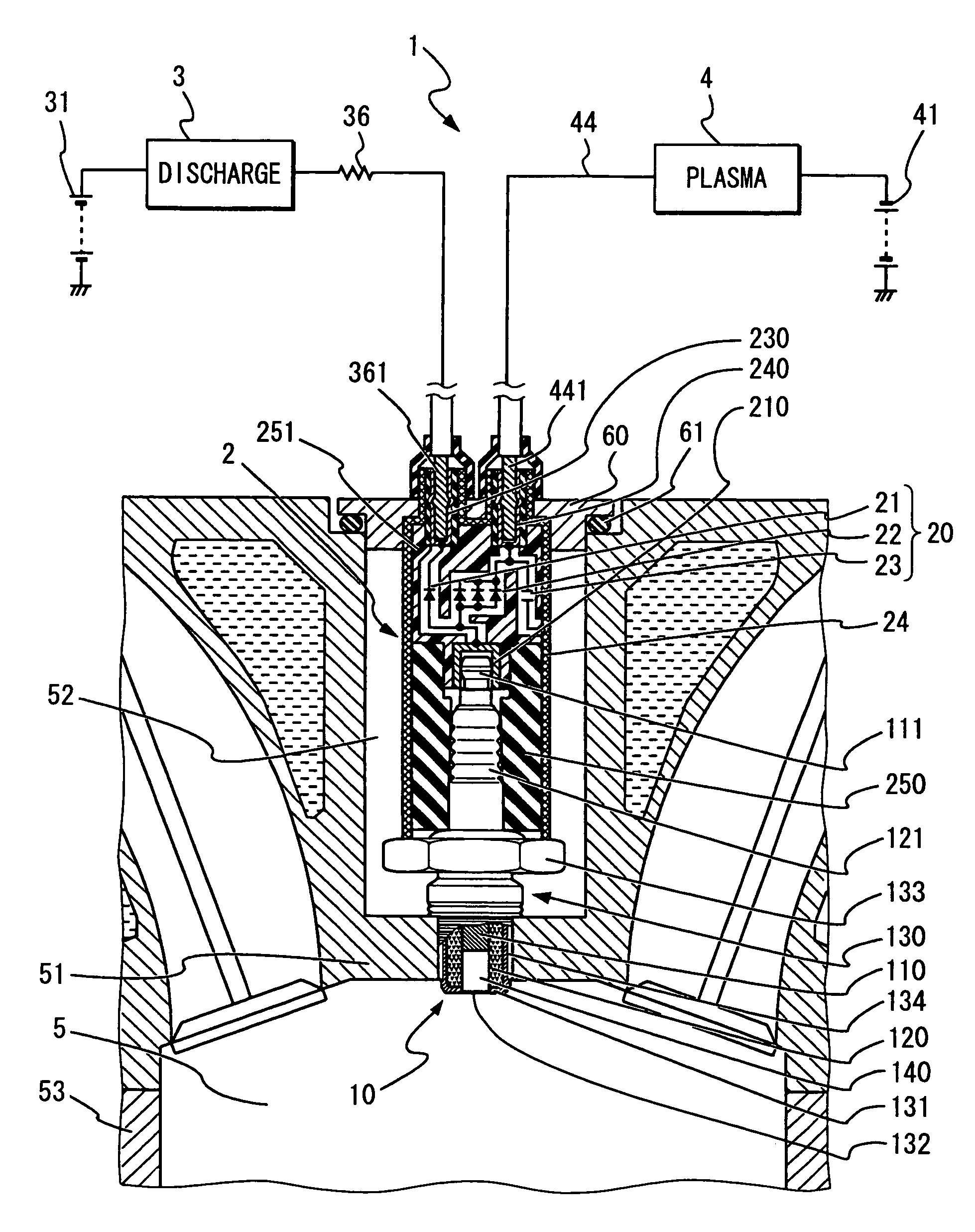
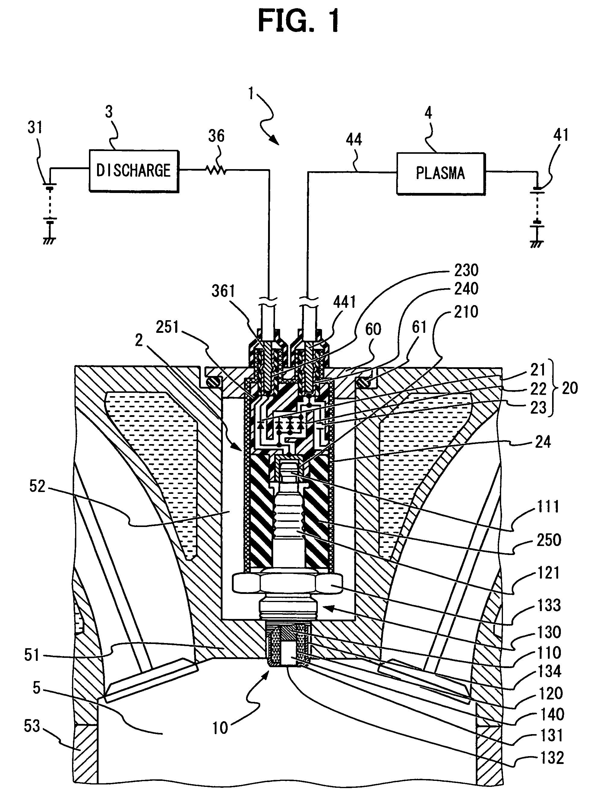
[0027]Referring first to FIG. 1, a plasma ignition system 1 has a plasma type ignition plug 10, an electromagnetic noise reduction circuit 20, a discharging power circuit 3, and a plasma generating power circuit 4. The noise reduction circuit 20 is provided within a plug cap 2 and connected to the discharging power circuit 3 and the plasma generating power circuit 4 via a discharging power supply electric wire (discharging wire) 36 and a plasma generating power supply electric wire (plasma generating wire) 44, respectively. The discharging power circuit 3 is connected to a positive terminal of a first battery 31. The plasma generating power circuit 4 is connected to a negative terminal of a second battery 4.

[0028]The ignition plug 10 is fitted in a plug hole 52 of an engine block 51 so that its top end is exposed into a combustion chamber 5 defined by an engine block 51, a cylinder block 53 and a piston (not shown). The ignition plug 10 has a center electrode 110, an insulator 120, ...

second embodiment

[0046]In a second embodiment, as shown in FIG. 5, the plug cap 2 is designed differently. That is, the second terminal 230 for connection to the discharging wire 36 and the third terminal 240 for connection to the plasma generating wire 44 are disposed in a perpendicular relation to each other, so that the plug cap 2 may be reduced in size. No fixing member is provided. Rather, by simply fitting the plug cap 2 onto the ignition plug 10 after tightly threading the ignition plug 10 into the engine block 51, the first terminal 210 connected to the second terminal 230 is fitted onto the terminal 111 of the center electrode 110. The case 24 is fitted onto the hexagonal part 133 and ground, while tightly fitting the insulating member 250 onto the insulator head 121 of the ignition plug 10.

[0047]The noise reduction circuit 20 is formed on an insulating substrate having good heat radiating property such as alumina or aluminum nitride, so that the first rectifier 21, the second rectifier 22 ...

third embodiment

[0049]In a third embodiment, as shown in FIG. 6, the plug cap 2 is constructed similarly to that in the second embodiment. It is however different in that the case 24 as the electromagnetic shield is fixed to a fixing part 510, while sandwiching the elastic member 61. The fixing part 510 is a protrusion formed integrally on the engine block 51. Since the engine block 51 functions as an electromagnetic shield, the case 24 has no cylindrical part, which covers the outer periphery of the insulating seal 250 in the plug hole 52. The case 24 therefore covers only a part exposed outside the plug hole 52 thereby restricting electromagnetic noise from leaking.


PUM


Abstract

A plasma ignition system has an electromagnetic noise reduction circuit in addition to a discharge power circuit, a plasma generating power circuit, a plasma ignition plug, a discharging wire and a plasma generating wire. The noise reduction circuit includes a first rectifier connected to the discharging wire, a second rectifier connected to the plasma generating wire, and a noise reducing capacitor connected in parallel to the second rectifier. The noise reduction circuit is disposed close to the ignition plug so that the noise reducing capacitor bypasses only high frequency noise currents generated when the ignition plug discharges.

Description

CROSS REFERENCE TO RELATED APPLICATION[0001]This application is based on and incorporates herein by reference Japanese Patent Applications No. 2006-342390 filed on Dec. 20, 2006 and No. 2007-156178 filed on Jun. 13, 2007.FIELD OF THE INVENTION[0002]The present invention relates to a plasma ignition system having a noise reduction circuit.BACKGROUND OF THE INVENTION[0003]A normal ignition system for an internal combustion engine of a vehicle, etc. has, as shown in FIG. 10A, an ignition plug 10, a battery 31, an ignition switch 32, an ignition coil 33, an electronic control unit (ECU) 35, an igniter (transistor) 34, and the like[0004]In this system, as shown in FIG. 10B, when the ECU 35 generates an ignition signal after the ignition switch 32 is turned on, the igniter 34 turns on so that a voltage (e.g., 12 V) of the battery 31 is applied to a primary winding 331 of the ignition coil 33 causing a primary current in the primary winding 331. When the ignition signal disappears and the ...

Claims


Application Information

Patent Timeline
Patent Type & Authority Patents(United States)
IPC IPC(8): F02P3/02F02P3/06
CPCF02P9/007F02P7/0638H01T13/05H01T13/52H01T13/41
Inventor KATOH, HIDEYUKIYOSHINAGA, TOORU
Owner DENSO CORP
Why Eureka
Try Eureka