Short sleeve stent delivery catheter and methods

a stent and short sleeve technology, applied in the field of short sleeve stent delivery catheter and methods, can solve the problems of wire crossing significantly reduced, facilitate catheter maneuvering within the patient, and achieve the effect of reducing the difficulty of wire crossing

Inactive Publication Date: 2008-06-17
BOSTON SCI SCIMED INC
View PDF14 Cites 43 Cited by
  • Summary
  • Abstract
  • Description
  • Claims
  • Application Information

AI Technical Summary

Benefits of technology

[0016]By advancing the catheter over a single guidewire, i.e., the branch vessel guidewire, the problem of wire crossing is significantly reduced. After the side sheath is near or into the branch vessel, the primary main guidewire may be further advanced into the main vessel.
[0017]In some cases, a physician will not want to lose wire placement and will therefore desired to maintain a guidewire within the main vessel at all times. In such cases, a secondary or back up main vessel guidewire may be inserted into the main vessel such that a distal end of the secondary main vessel guidewire passes beyond the ostium of the branch vessel prior to inserting the catheter over the branch vessel guidewire. Once the catheter is near the ostium and the primary main vessel guidewire has been advanced through the catheter, the secondary main vessel guidewire may be withdrawn prior to inflation of the balloon. If the branch vessel guidewire and the secondary main vessel guidewire cross, the catheter body may be torqued during insertion in order to overcome the wire crossing. The wire crossing may be overcome since the secondary main vessel guidewire runs along side of the catheter. Since the profile of the catheter may be relatively small, maneuvering of the catheter within the patient is also facilitated.

Problems solved by technology

This condition may prevent the successful delivery of the catheter system by impeding its travel and, subsequently, the alignment of the stent's side opening with the ostium of the branch vessel.

Method used


Image

  • Short sleeve stent delivery catheter and methods
  • Short sleeve stent delivery catheter and methods
  • Short sleeve stent delivery catheter and methods

Examples


Embodiment Construction

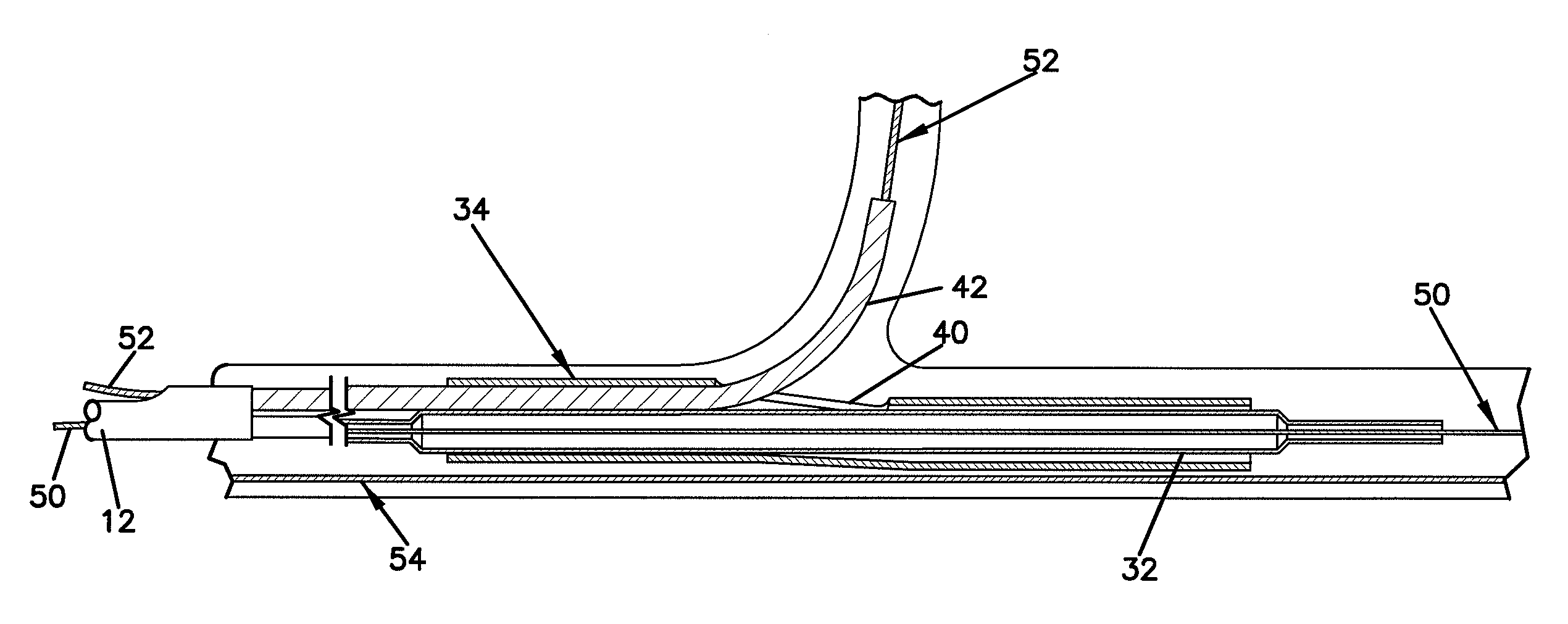
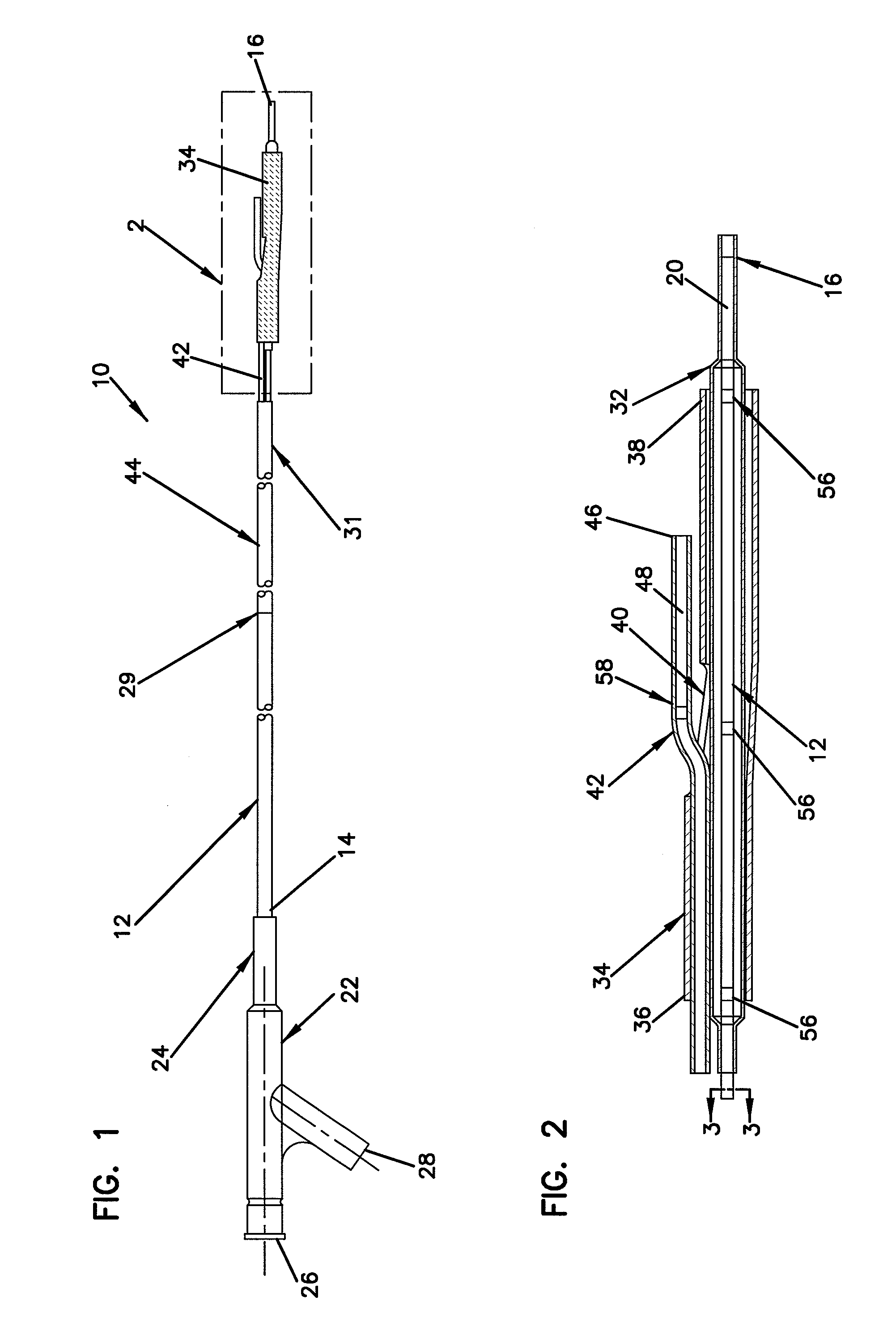
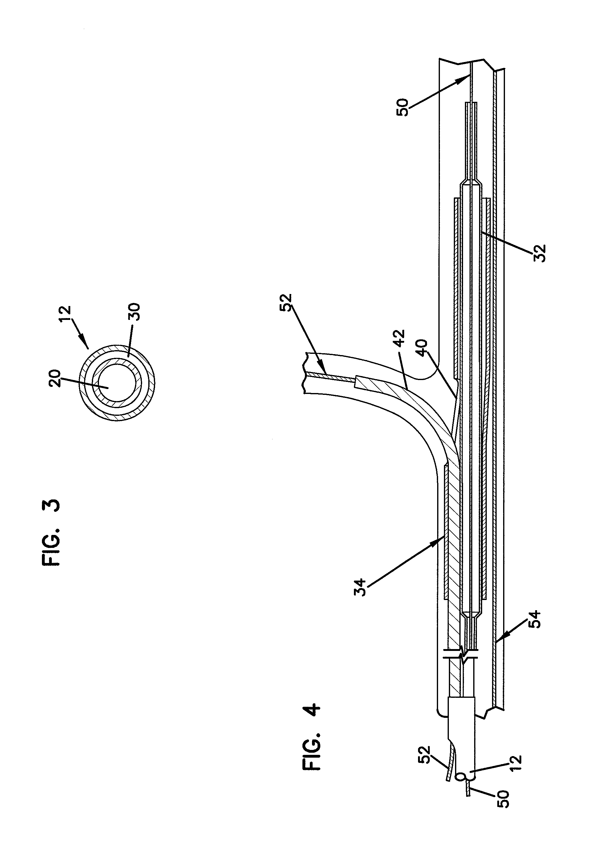
[0031]In one aspect, the invention provides systems and methods for deploying stents at a vessel bifurcation such that a cell in the stent that is specifically designed to function as a branch aperture (referred to herein as a side hole of the stent) is in registry with the ostium of the branch vessel. Further, various techniques are provided for managing the guidewires over which the stents and stent delivery catheters are directed. More specifically, the invention provides techniques to help prevent the crossing of guidewires or to traverse crossed guidewires when introducing catheters used to deploy stents or other devices that require advancement over multiple guidewires, where it is important for the guidewires to be tangle free and parallel with respect to each other. In this way, the catheters may more easily be introduced to the diseased region.

[0032]The invention also provides techniques for reducing the profile of such delivery catheters, and to facilitate the introduction...


PUM


Abstract

A stent delivery catheter comprises a catheter body having a proximal end, a distal end, and a guidewire lumen extending from the distal end to at least part way between the proximal end and the distal end. A balloon is disposed over the catheter body near the distal end, and a stent is positioned over the balloon. The stent has a proximal end, a distal end, and a side opening between the proximal end and the distal end. A side sheath is coupled to the catheter body and has a proximal end, a distal end, and a guidewire lumen extending between the proximal end and the distal end. The proximal end of the side sheath is located between the proximal end of the catheter body and the balloon, and the side sheath exits out of the side opening of the stent.

Description

CROSS-REFERENCES TO RELATED APPLICATIONS[0001]This application is a continuation-in-part of U.S. patent application Ser. No. 09 / 325,996, filed Jun. 4, 1999, entitled “CATHETER WITH SIDE SHEATH,” the disclosure of which is herein incorporated by reference. This application claims priority to 09 / 325,996 to the extent appropriate by law.[0002]This application also is a continuation-in-part of U.S. patent application Ser. No. 09 / 455,299, filed Dec. 6, 1999, entitled “CATHETER WITH ATTACHED FLEXIBLE SIDE SHEATH,” the disclosure of which is herein incorporated by reference. This application claims priority to 09 / 455,299 to the extent appropriate by law.[0003]This application also is a continuation-in-part of U.S. patent application Ser. No. 09 / 614,472, filed Jul. 11, 2000, entitled “CATHETER WITH SIDE SHEATH,” which is a continuation-in-part of said 09 / 325,996, and which is a continuation-in-part of said 09 / 455,299. The disclosure of said 09 / 614,472 is herein incorporated by reference. Th...

Claims


Application Information

Patent Timeline
Patent Type & Authority Patents(United States)
IPC IPC(8): A61F2/82A61F2/06A61F2/84A61M25/12
CPCA61F2/954A61F2/958A61F2/856
Inventor BOURANG, HENRYPATEL, UDAYAN G.VARDI, GIL M.FARIABI, SEPEHRWILLIAMS, ERICSAGASTEGUI, JAVIERDAVIDSON, CHARLES
Owner BOSTON SCI SCIMED INC
Why Eureka
Try Eureka