Microwave oven having a driving unit for moving and rotating an antenna
a technology of driving unit and microwave oven, which is applied in the direction of domestic stoves or ranges, lighting and heating apparatus, heating types, etc., can solve the problems of limited size and shape of food to be introduced in the cooking chamber b>4/b>, and achieve the effect of improving cooking performance, increasing the space of the cooking chamber, and facilitating the cleaning process
- Summary
- Abstract
- Description
- Claims
- Application Information
AI Technical Summary
Benefits of technology
Problems solved by technology
Method used
Image

Examples
first embodiment
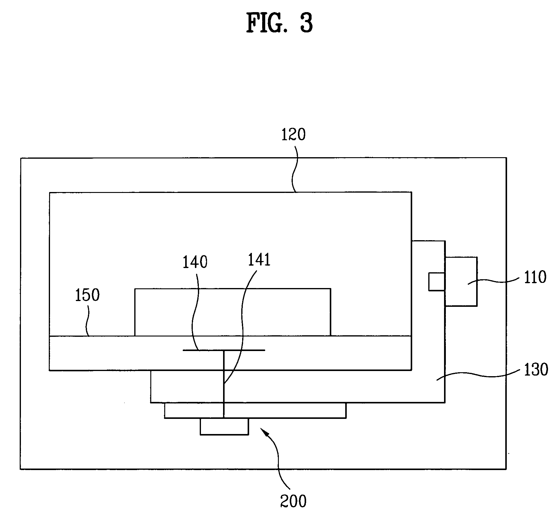
[0033]FIG. 3 illustrates a diagram of a microwave oven in accordance with the present invention. FIG. 4 illustrates a front section showing some parts in FIG. 3. FIG. 5 illustrates a side section showing some parts in FIG. 3. FIG. 6 illustrates a perspective exploded view showing some parts in FIG. 3. Referring to FIGS. 3-6, the microwave oven includes a cooking chamber 120, a magnetron 110, a waveguide 130, an antenna 140, a flat plate 150, and a driving unit 200.
[0034]The cooking chamber 120 forms a space for cooking food. The magnetron 110 is outside the cooking chamber 120, for generating the microwave to cook the food. The waveguide 130 between the magnetron 110 and the cooking chamber 120 for guiding the microwave from the magnetron 110 into the cooking chamber 120. The antenna 140 between the cooking chamber 120 and the waveguide 130 propagates the microwave guided by the waveguide into the cooking chamber 120.
[0035]The flat plate 150 is over the antenna 140 for placing food ...
second embodiment
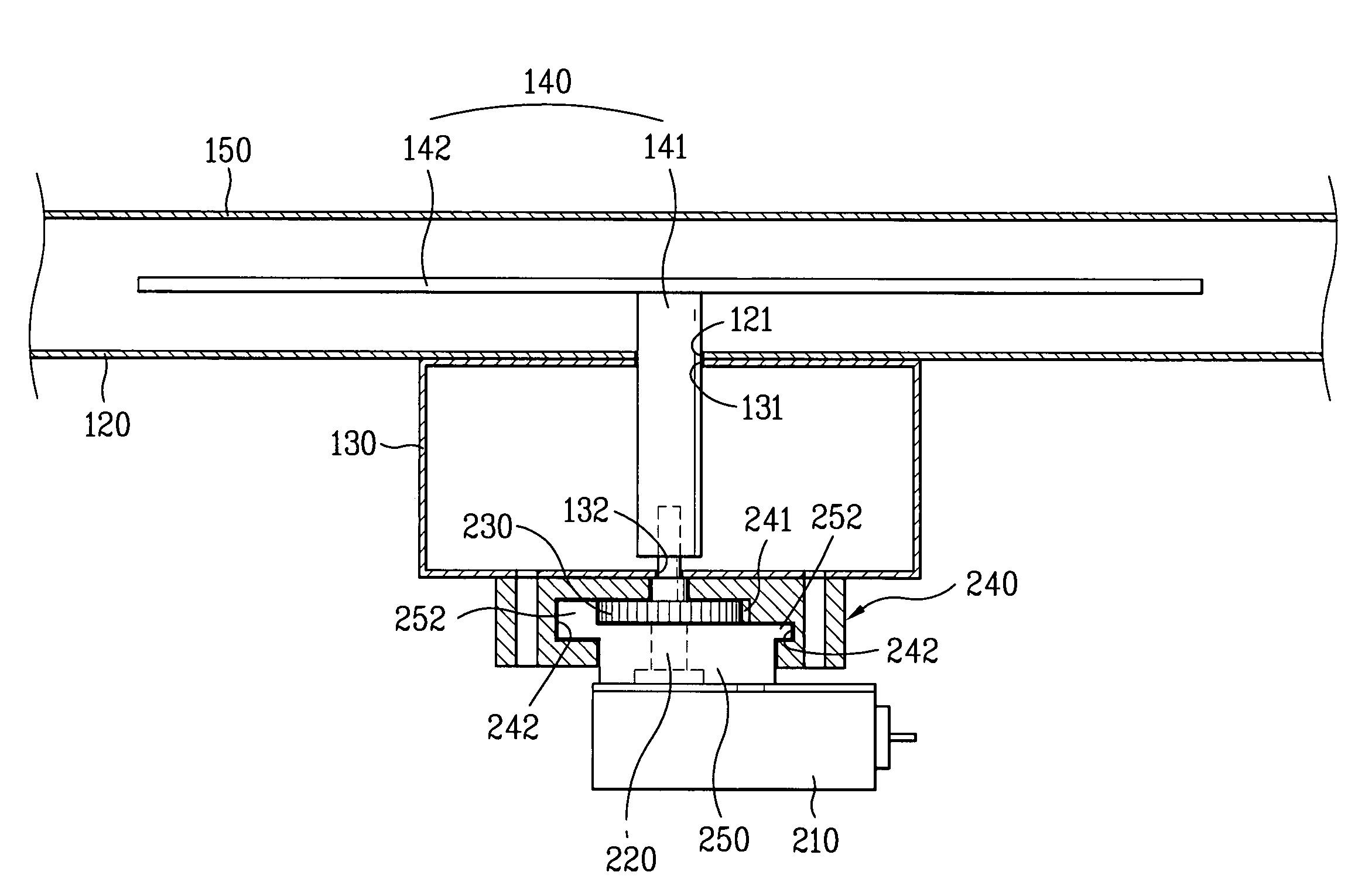
[0050]The microwave oven in accordance with the present invention includes the pinion 230 provided to the outer circumferential surface of the shaft 141 of the antenna 140. The antenna 140 at the lower end of the shaft 141 thereof is connected to the motor 210 at the motor shaft 220 thereof.
[0051]That is, referring to FIGS. 7 and 8, the shaft 141 of the antenna 140 passes through the pinion 230, and the lower end of the shaft 141 of the antenna 140 projects through the lower surface of the waveguide 130, and is connected to the motor rotation shaft 220 directly. In order to reciprocally move the shaft 141 of the antenna 140, the waveguide 130 has slots 131 and 132 at its upper and lower surfaces thereof respectively, and the cooking chamber 120 also has a slot 121 at its lower surface.
[0052]Because the structure and operation of the microwave oven of the second embodiment of the present invention are similar to the first embodiment except the above, the detailed description of other...
third embodiment
[0055]Referring to FIGS. 9 and 10, the driving unit in the third embodiment includes a motor 410, a motor shaft 420, a pinion 430, a housing 440, a guide member 450, a connection link 460, and a rotation link 470.
[0056]The motor 410 rotates in one direction, and is provided with a motor shaft 420 for transmitting a rotation force. The pinion 430 is mounted to the outer circumferential surface of the shaft 141 of the antenna 140.
[0057]The housing 440 has an opened upper surface for receiving the lower end of the shaft 141 of the antenna 140 projected outwardly through the lower surface of the waveguide 130.
[0058]The guide member 450 is fixedly secured inside the housing 440, and has a rack 451 arranged in a length direction corresponding to the pinion 430. The connection link 460 has one end swingably connected to the lower end of the shaft 141 of the antenna 140, and the other end extended as a free end. The rotation link 470 has one end swingably connected to the other end of the c...
PUM
 Abstract
Description
Claims
Application Information
 - R&D
- Intellectual Property
- Life Sciences
- Materials
- Tech Scout
- Unparalleled Data Quality
- Higher Quality Content
- 60% Fewer Hallucinations
Browse by: Latest US Patents, China's latest patents, Technical Efficacy Thesaurus, Application Domain, Technology Topic, Popular Technical Reports.
© 2025 PatSnap. All rights reserved.Legal|Privacy policy|Modern Slavery Act Transparency Statement|Sitemap|About US| Contact US: help@patsnap.com