Supercharge Your Innovation With Domain-Expert AI Agents!

System and method for connecting electrical devices using fiber optic serial communication

a technology of serial communication and electrical devices, applied in the field of connecting electrical devices, can solve the problems of limited rs485, damage to one or more devices of the network, and disrupt communication

Inactive Publication Date: 2008-06-17
ELECTRO INDUSTRIES GAUGE TECH
View PDF26 Cites 6 Cited by
  • Summary
  • Abstract
  • Description
  • Claims
  • Application Information

AI Technical Summary

Benefits of technology

The present patent provides circuitry and methods for connecting a device to a network of electrical devices using light signals. The circuitry includes an input channel for receiving a light signal from a preceding electrical device, light to voltage converter circuitry for converting the light signal to a voltage signal, a processor for processing the voltage signal, and output channel for outputting the light signal to a subsequent electrical device. The light signals are propagated between the electrical devices primarily via fiber optic connectors. The technical effects include improved communication between electrical devices in a network and increased efficiency in data transfer.

Problems solved by technology

However, the RS485 is limited in accordance with speed constraints inherent to propagation speeds along electrically conductive cable (e.g., copper cable).
Additionally, the electrically conductive cable is inherently susceptible to noise, poor grounding, power surges and attenuation of propagated signals towards the end of the chain, which may disrupt communication and / or cause damage to one or more devices of the network.
The RTU and / or meters may be located in environments in which electrical activity, including high voltage, current and / or power conditions, may generate electromagnetic fields and / or other conditions which typically cause detrimental noise along electrically conductive cable and / or may cause damage to respective hardware.
However, the connections between the devices are still electrical and prone to noise, electrical transients, arcing, etc., particularly when in proximity to a high degree of electrical activity.
However, multiple data streams may result in catastrophic data collisions.

Method used


Image

  • System and method for connecting electrical devices using fiber optic serial communication
  • System and method for connecting electrical devices using fiber optic serial communication
  • System and method for connecting electrical devices using fiber optic serial communication

Examples


Embodiment Construction

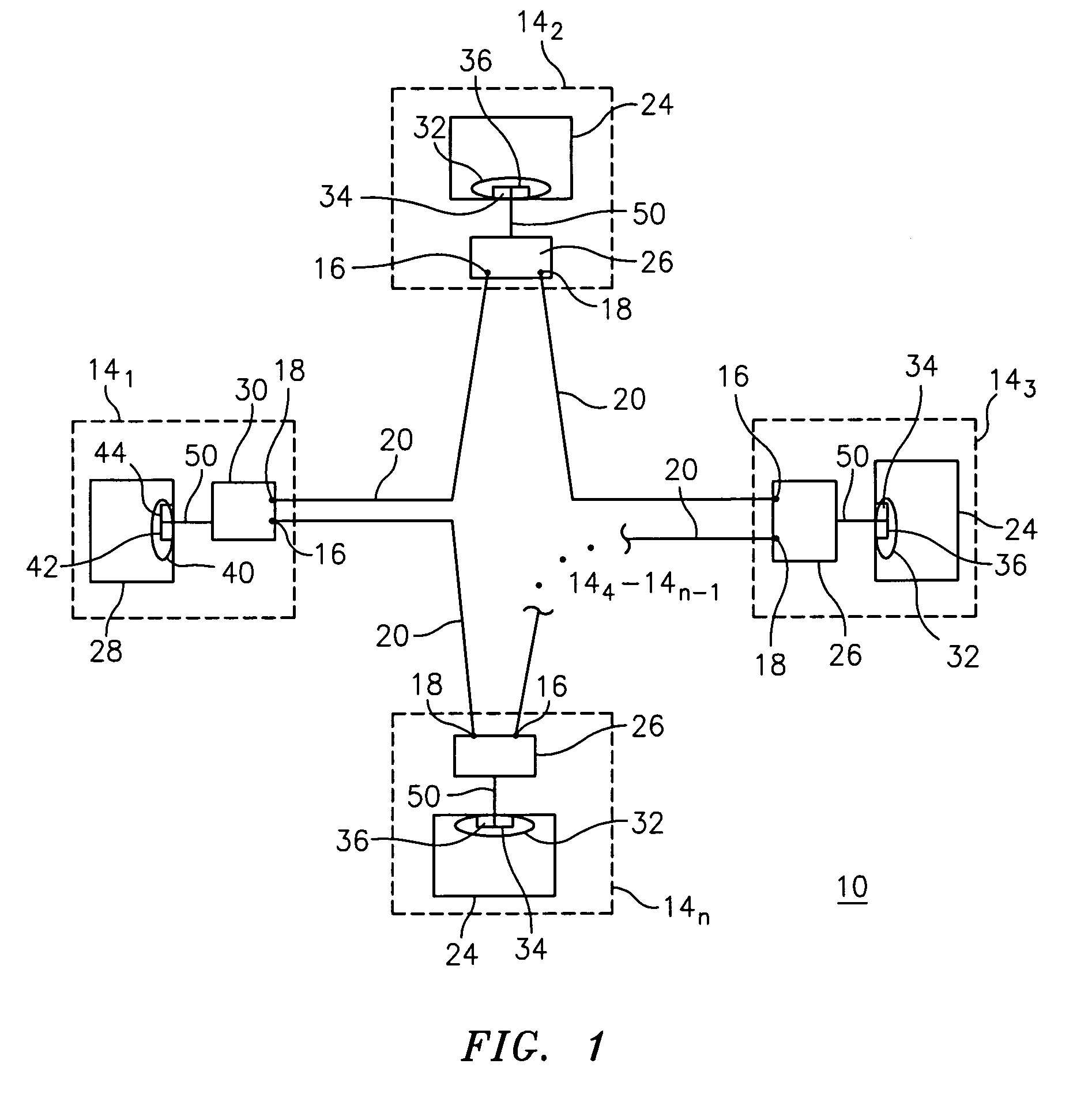
[0020]With respect to FIG. 1, a network of electrical devices 10 is shown. The network 10 includes electrical devices 14 communicatively connected in a series, where the series includes n devices 141-14n. One of the devices 14, shown as device 141, is a master device, while the remaining devices 142-14n are slave devices. The devices each have an input channel 16 and an output channel 18. The series of devices 14 are connected in series in a closed loop for forming a closed communication ring, in which the output channel 18 of respective devices 14 is communicatively connected to the input channel 16 of a subsequent device 14, in the series, which is preferably the next device 14 in the series. The output channel 18 of device 14n is communicatively connected to the input channel 16 of the master device 141.

[0021]Devices (preferably adjacent devices) in the series are communicatively connected via fiber optic connectors 20 for transmitting light signals between the connected devices ...


PUM

PropertyMeasurementUnit
electrical poweraaaaaaaaaa
voltageaaaaaaaaaa
timeaaaaaaaaaa

Abstract

A system and method for communicating between serially connected electrical devices of a network is provided. The network includes a series of electrical devices, and fiber optic connectors between electrical devices of the series of electrical devices forming a closed communication ring in which output of each electrical device is communicatively connected to input of a subsequent electrical device of the series of electrical devices.

Description

[0001]This application claims priority under 35 U.S.C. §119 to U.S. Provisional Application Ser. No. 60 / 622,479, filed on Oct. 27, 2004, and entitled “Fiber Optic Daisy Chain for Electrical Devices / Meters”, the entire contents of which are expressly incorporated herein in their entirety.BACKGROUND OF THE INVENTION[0002]1. Field of the Invention[0003]This invention relates to connecting electrical devices. In particular, this invention relates to a system and method for connecting electrical devices using a fiber optic serial communication configuration.[0004]2. Description of the Related Art[0005]In a master / slave configuration, digital communication is provided between a master device and a plurality of slave devices so that the master may communicate with individual slaves. One configuration is a serial communication (e.g., daisy chain) configuration in which an input channel or port of each device is connected to an output channel or port of an adjacent device, forming a closed r...

Claims


Application Information

Patent Timeline
Patent Type & Authority Patents(United States)
IPC IPC(8): G01J1/04G01J1/42G02F1/00H04B10/00H04B10/08
CPCH04B10/2755
Inventor SPANIER, JOSEPHBANHEGYESI, TIBOR
Owner ELECTRO INDUSTRIES GAUGE TECH
Features
  • R&D
  • Intellectual Property
  • Life Sciences
  • Materials
  • Tech Scout
  • Unparalleled Data Quality
  • Higher Quality Content
  • 60% Fewer Hallucinations
Learn More