Image heating apparatus and flexible sleeve used for the same

a technology of heating apparatus and flexible sleeves, which is applied in the direction of electrographic process apparatus, instruments, optics, etc., can solve the problems of reducing the flexibility of the flexible sleeves, difficult to ensure the durability for long time use, and difficulty in reducing the thickness of the metal sleeves, etc., to achieve the effect of ensuring durability

Active Publication Date: 2008-06-17
CANON KK
View PDF22 Cites 26 Cited by
  • Summary
  • Abstract
  • Description
  • Claims
  • Application Information

AI Technical Summary

Benefits of technology

[0009]The present invention has been made in view of the above-mentioned problems, and therefore, an object of the present invention is to provide an image heating apparatus capable of ensuring durability even with the use of a stainless base layer having an outer diameter of 18 mm to 24 mm and a flexible sleeve used for the image heating apparatus.

Problems solved by technology

However, if the diameter of the flexible metal sleeve is reduced in the case where the flexible metal sleeve is used as the fixing film, because a curvature radius becomes small, a flexural strength decreases.
However, there is a problem in that a process of reducing the thickness of the metal sleeve is difficult.
However, when the outer diameter of the stainless sleeve is reduced to 18 mm to 24 mm, it is difficult to ensure the durability for long time use even when the thickness of the stainless sleeve is reduced to about 25 μm to 30 μm.
Therefore, it is technically difficult to mount the stainless sleeve having the outer diameter of 18 mm to 24 mm to the film heating type fixing apparatus.

Method used


Image

  • Image heating apparatus and flexible sleeve used for the same
  • Image heating apparatus and flexible sleeve used for the same
  • Image heating apparatus and flexible sleeve used for the same

Examples


first embodiment

[0031](1) Example of an Image Forming Apparatus

[0032]FIG. 14 is a structural model view of an example of an image forming apparatus to which an image heating apparatus according to the present invention can be mounted as an image heating fixing apparatus. The image forming apparatus is an electrophotographic laser beam printer.

[0033]The image forming apparatus includes the drum type of electrophotosensitive member (hereinafter, referred to as “photosensitive drum”) 11 serving as an image bearing member, a charging roller 12 serving as charge means, a laser exposure device 10, and a developing device 13 serving as developing means.

[0034]The photosensitive drum 11 is, for example, an organic photosensitive drum including a photosensitive layer of an organic photoconductive member or the like formed on an outer circumferential surface of an electroconductive drum base made of aluminum or the like.

[0035]The charging roller 12 uniformly performs a charging process on an outer circumferen...

second embodiment

[0079]Another example of the metal sleeve according to the present invention will be described. In this embodiment, the members and parts common to those in the first embodiment are denoted by the same reference numerals, so the overlapping description thereof is herein omitted. The same is also applied to the following third and fourth embodiments.

[0080]FIG. 8 is a transverse sectional view of the metal sleeve 33 according to this embodiment.

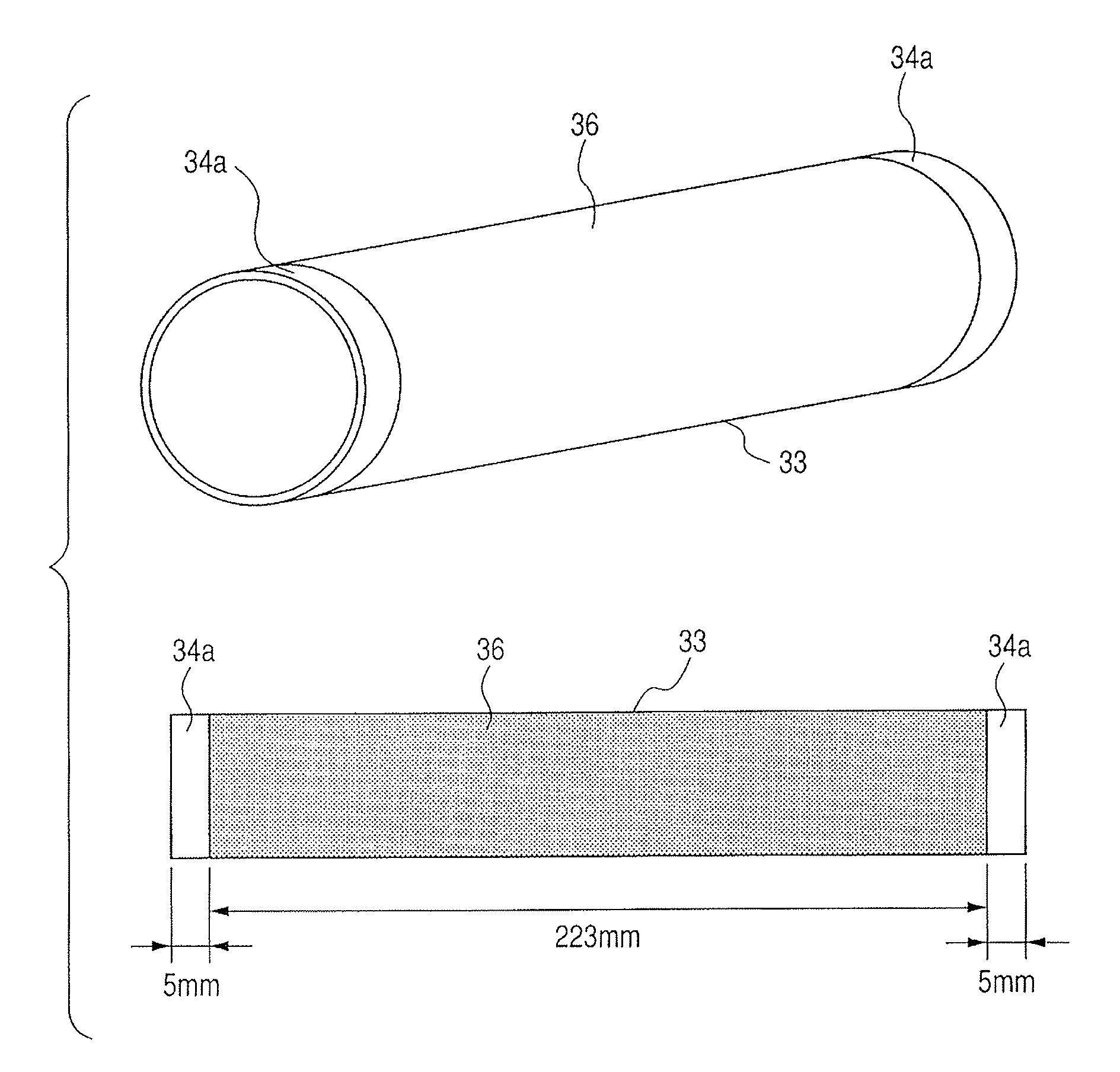
[0081]In this embodiment, a sleeve made of a stainless steel (SUS 304S), which has an outer diameter of 18 mm, a thickness of 27 μm and a length of 233 mm, is used as the sleeve base (stainless base layer) 34. The entire outer circumferential surface of the sleeve base 34 was sandblasted with abrasive grains of about #400. A time length and an air discharge pressure of the blast process are the same as those in the first embodiment. After the blast process, a fluorine resin layer was thermally welded onto the outer circumferential surface of th...

third embodiment

[0092]A further example of the metal sleeve according to the present invention will be described.

[0093]In this embodiment, a sleeve made of a stainless steel (SUS 304L), which has an outer diameter of 24 mm, a thickness of 30 μm and a length of 233 mm, is used as the sleeve base 34. The entire outer circumferential surface of the sleeve base 34 was sandblasted with abrasive grains of about #400. A time length and an air discharge pressure of the blast process are the same as those in the first embodiment. As in the second embodiment, after the blast process, the outer circumferential surface of the sleeve base was covered with a heat-shrinkable PFA tube having a thickness of 15 μm as the surface layer 36 and was then heated at 350° C. for several hours to thermally weld the PFA tube 36 onto the outer circumferential surface of the sleeve base 34.

[0094]When the stainless base layer of the metal sleeve 33 used in this embodiment is cut open straight in a longitudinal direction (genera...


PUM


Abstract

The image heating apparatus includes a flexible sleeve including a stainless base layer; a heater being in contact with an inner circumferential surface of the flexible sleeve; and an elastic roller being in contact with an outer circumferential surface of the flexible sleeve and forming a nip portion with the heater, in which: a recording material bearing an image is heated while being pinched and conveyed at the nip portion; and the stainless base layer has an outer diameter of 18 mm to 24 mm and a thickness of 25 μm to 30 μm, and includes an outer circumferential surface being subjected to a blasting process. Bu the present invention, an image heating apparatus is capable of ensuring durability and a flexible sleeve used for the image heating apparatus.

Description

[0001]This application is a continuation of International Application No. PCT / JP2007 / 052905 filed on Feb. 13, 2007, which claims the benefit of Japanese Patent Application No. 2006-036466 filed on Feb. 14, 2006, and Japanese Patent Application No. 2007-029067 filed on Feb. 8, 2007.BACKGROUND OF THE INVENTION[0002]1. Field of the Invention[0003]The present invention relates to an image heating apparatus suitable for use as an image heating fixing apparatus mounted to an image forming apparatus such as an electrophotographic copying machine and an electrophotographic printer, and to a flexible sleeve used for the image heating apparatus.[0004]2. Description of the Related Art[0005]As an image heating fixing apparatus (fixing device) to be mounted to an image forming apparatus such as an electrophotographic copying machine or a printer, there exists a film heating type apparatus. The film heating type fixing apparatus includes a heater having a resistance heat generating member on a su...

Claims


Application Information

Patent Timeline
Patent Type & Authority Patents(United States)
IPC IPC(8): G03G15/20
CPCG03G15/2053
Inventor NARAHARA, TAKASHISUZUMI, MASAHIKOASAMI, JUNMATSUZAKA, KENJI
Owner CANON KK
Why Eureka
Try Eureka