Methods to prevent wheel slip in an autonomous floor cleaner

a technology of floor cleaners and wheels, applied in the direction of process and machine control, distance measurement, instruments, etc., can solve the problems of device to remain in place, device to divert, wheel of such devices may slip

Active Publication Date: 2008-06-17
SC JOHNSON & SON INC
View PDF50 Cites 161 Cited by
  • Summary
  • Abstract
  • Description
  • Claims
  • Application Information

AI Technical Summary

Benefits of technology

[0013]In connection with such a tread design, it is desirable to make the contact area of the tire as small as possible, so that more of the weight of the device is borne in a small area of contact. This helps drive the contact surface down through any pooling liquid. A preferred way to achieve this is to form the tire in a sprocket shape with the radial edges of the sprocket being very small rectangular areas. Such a structure also has advantages for gripping a carpet.
[0035]During operation of the robotic device, the controller executes a stored program to calculate a first amount of slip for the first wheel from the first wheel rotation signals received from the means for measuring wheel rotation, and calculate a second amount of slip for the second wheel from the second wheel rotation signals received from the means for measuring wheel rotation. When the first amount of slip exceeds a predetermined first value of slip or the second amount of slip exceeds a predetermined second value of slip, the controller provides fluid delivery signals to the means for delivering a fluid such that fluid is not delivered onto the sheet cleaning material. In this manner, the device can temporarily stop applying liquid floor cleaner until wheel slip subsides.

Problems solved by technology

While devices of this type can work quite well on dry surfaces, the wheels of such devices may slip when traveling over areas of the floor that are wet from the fluid being applied.
This is particularly likely when the liquid itself is of the type which, when wet, is significantly more slippery than water (e.g. contains oil for polishing purposes).
Such slipping can cause the device to remain in place for an extended period, or more likely cause the device to divert in an unexpected direction from the optimal desired path.
This can extend the time needed to treat the surface, and / or can lead to portions of the surface not being adequately treated.
However, many of these approaches are designed to take advantage of the very heavy weight of such vehicles, and are not easily transferred to environments where a cleaning robot is involved that weighs much less.
Others of these approaches rely on expensive materials, or structures that are relatively expensive to create.
Because such controller systems were designed for extremely heavy vehicles, they were not easily transferred to environments where a cleaning robot was involved that weighed much less.
Further, some systems that could be transferred to a small cleaning robot were of too great a cost to be used in that environment as a practical matter.

Method used


Image

  • Methods to prevent wheel slip in an autonomous floor cleaner
  • Methods to prevent wheel slip in an autonomous floor cleaner
  • Methods to prevent wheel slip in an autonomous floor cleaner

Examples


Embodiment Construction

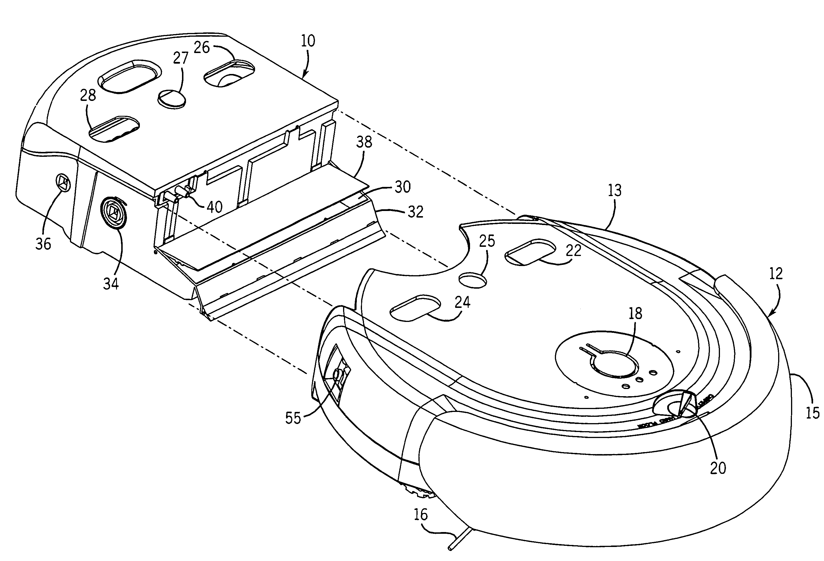
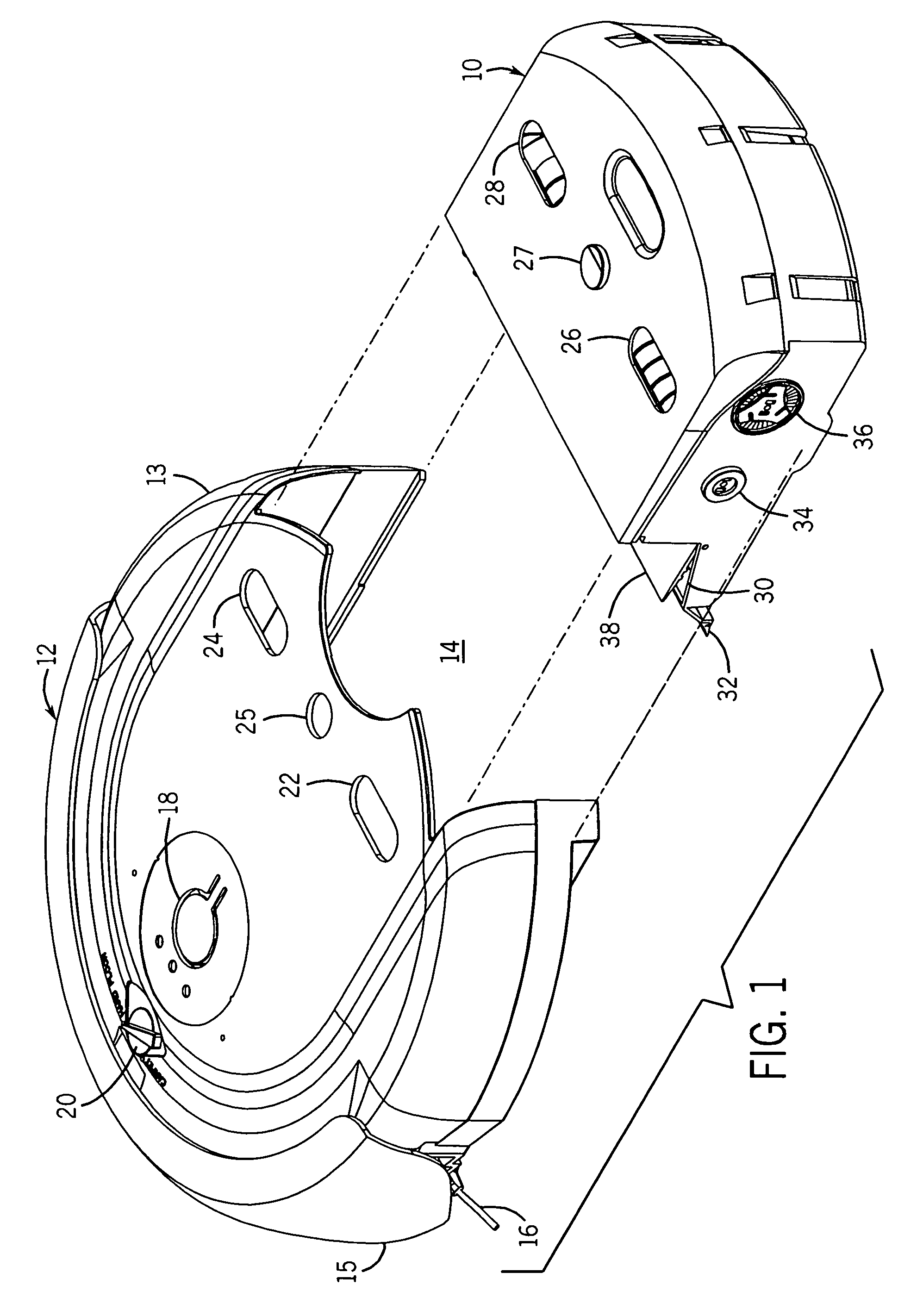
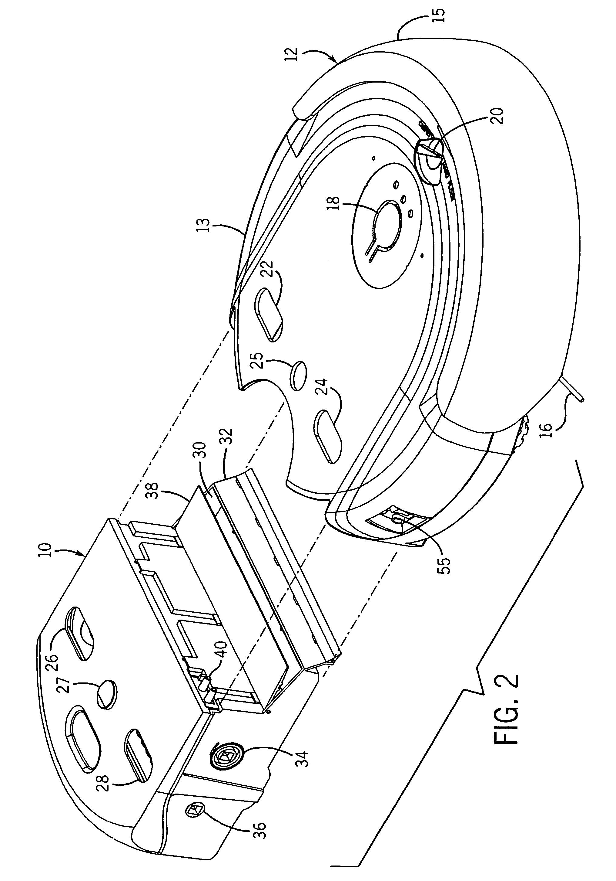
[0052]We first describe example autonomous cleaning devices with reference to FIGS. 1-11. This provides examples of environments where the invention of the present invention can be applied. Thereafter, we describe with reference to FIGS. 12-15 specific features of the present invention.

[0053]It should be understood that the present invention is also suitable for use with many other types of autonomous treating devices. Thus, the invention is not intended to be restricted to just cleaning devices, much less devices having the specific attributes shown in FIGS. 1-11.

[0054]Referring particularly to FIGS. 1 and 3, there is a cleaning cartridge 10 suitable to be inserted into a cleaning device 12. The cleaning cartridge 10 has a roll of sheet cleaning material 44 which is provided in a reel-to-reel configuration. A portion of the roll is maintained in contact with the surface below the cleaning device 12 at any given time during operation. A motor 52 is provided in the cleaning device 12...


PUM


Abstract

Tread structures, wave motion navigational controls, and ramp up recovery controls are provided to an autonomous floor cleaner to reduce wheel slippage. The floor cleaner delivers liquid to the floor as part of the cleaning process. Wheels on the device are provided with relatively deep peripheral grooves to minimize the contact surfaces of a sprocket wheel and to accommodate the layer of liquid on the floor. In the event of wheel slippage, or to prevent wheel slippage, the device is designed to move forward with a slight side-to-side wave action caused by periodically altering the relative speeds of two drive wheels. There is also provided a slippage recovery mode where the drive wheels shut down or greatly slow when severe slippage is sensed, followed by a slow ramp up of speed.

Description

CROSS-REFERENCE TO RELATED APPLICATIONS[0001]Not applicableSTATEMENT REGARDING FEDERALLY SPONSORED RESEARCH / DEVELOPMENT[0002]Not applicableBACKGROUND OF THE INVENTION[0003]It is desirable to minimize the amount of human labor expended in maintaining and cleaning buildings. The art has therefore developed autonomous robotic devices that can clean or otherwise maintain or treat hard floors, carpeting and similar surfaces without the necessity for a human to be present during the operation of the device.[0004]In some such devices a liquid is applied to the flooring area being treated. For example, U.S. Pat. No. 5,279,672 discloses a robotic cleaning apparatus where a cleaning solution is dispensed to the floor by a scrub deck. In U.S. Pat. No. 6,741,054 there is disclosed an autonomous floor mopping apparatus where cleaning fluid is applied to the floor by way of a pre-moistened towel.[0005]Such robotic devices typically have a programmable controller for directing the device in a pref...

Claims


Application Information

Patent Timeline
Patent Type & Authority Patents(United States)
IPC IPC(8): G05D1/00
CPCG05D1/0272G05D2201/0203
Inventor HARWIG, JEFFREY L.JAWORSKI, THOMASCHENG, FUKYUENCHEN, SEAKEE
Owner SC JOHNSON & SON INC
Why Eureka
Try Eureka